How to modify an AT / ATX computer power supply to a 3-15V bench power supply
Halfbridge topology power supply mod:
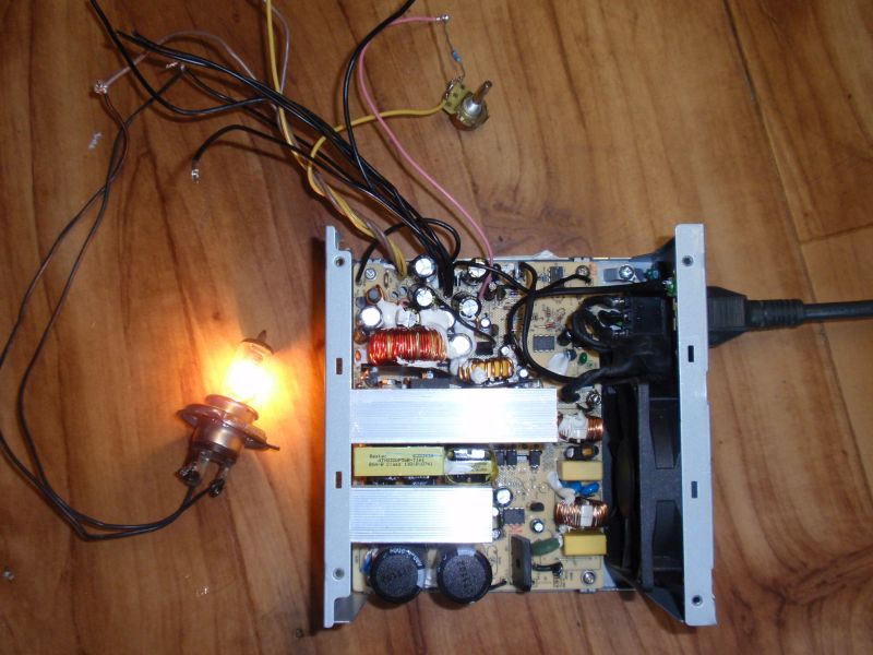
Everyone sometimes needs an adjustable power supply. Bench power supplies are expensive and therefore we usually use what's available.
The most well known power supplies of a high current low voltage are AT or ATX supplies from computers. Their disadvantage is a poorly regulated output voltage and often
a need to load both of the two main outputs (5 and 12V) at the same time. Therefore, I present a simple modification of an AT or ATX PC power supply to
an adjustable bench power supply of 3 - 15V with a proper regulation and an output current corresponding to the original 12V output.
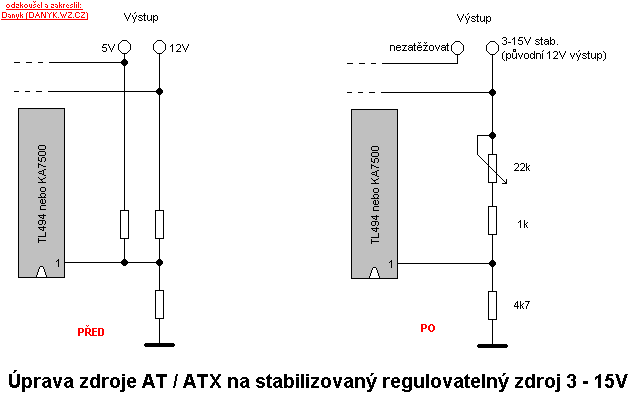
The voltage feedback is connected to pin 1 of TL494 control chip
(or its equivalent KA7500, KIA494, DBL494 ...). The reference voltage is 2.5 V (i.e. the circuit regulates the output voltage so that
the voltage of the resistive divider is 2.5 V). Originally the feedback is connected to both 5 and 12V outputs and
it works well only when both outputs are loaded. After this modification,
the feedback is only connected to the 12V output. A potentiometer regulates the voltage from 3 to 15 V. The potentiometer can be replaced by
a fixed resistor to set a constant voltage if needed. The ATX supply fan can be connected to the 5VSB so that it is not affected by the voltage adjustment.
During the modification you can find useful the AT and ATX computer power supplies schematics.
AT or ATX PC power supply outputs:
Yellow ... 12V
Red ... 5V
Black ... 0V (GND or COM)
Green ... Standby power. This is only present in ATX. Connect it to black (0V) to turn the supply on.
WARNING !!!
There's a dangerous lethal mains voltage inside the power supply.
Capacitors can remain charged dangerously even after disconnected from mains. Inappropriately modified power supply can be dangerous.
You do everything on your own risk.
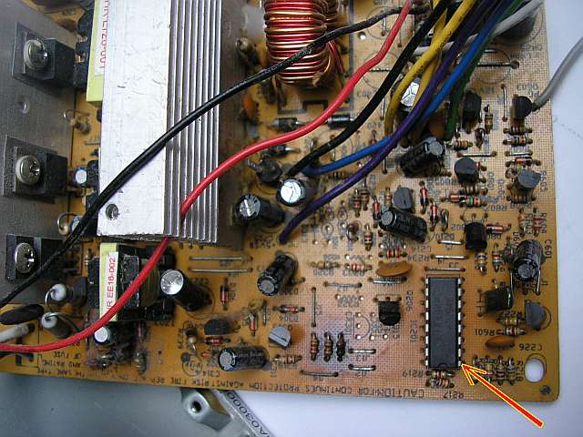
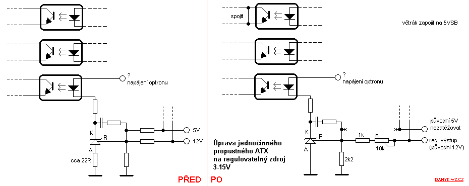
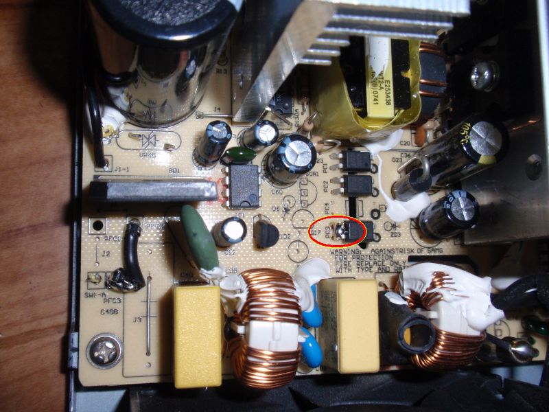
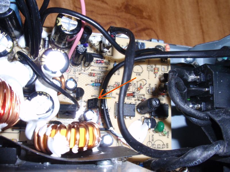
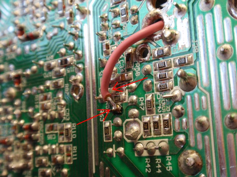
There are some ATX power supplies, which use so-called single switch forward topology with a single MOSFET (that tends to be rated 800-900V). In these supplies there's no TL494 chip. There's usually UC3843 and is on the primary side. Feedback is introduced via optocouplers. Voltage is sensed by TL431 (GL431, AZ431 - letters may vary). This circuit also has a 2.5V reference, so the principle is similar. From the reference pin (R) resistors go again to the ground, +5V and +12V. Moreover, there is an RC network between the reference input and cathode, it is necessary to leave it as it is. An adjustable resistor divider is seen in the schematic below. If the TL431 has the anode resistor (in the picture it is 22R), short it. Furthermore, it is necessary to enable the main power supply and eliminate the protection against undervoltage and overvoltage at the output. This is done by shorting the emitter and collector of one of the optocouplers (there are a total of 3-4). This is the optocoupler, which provides the standby function. Connecting the green wire (PS ON) to the ground is no longer necessary. After this modification the supply no longer shuts down when in short circuit - it enters into a current limiting mode. Short-circuit current is probably too high, therefore you should set the current limit a bit lower. It is done by replacing the current sensing resistor (shunt) by a higher value. This resistor is connected between the Source of the main MOSFET and the negative of the primary side. I suppose nobody will have problem to find this resistor. In my case there was 0R15 resistor rated 2W, it should be replaced with around 0R27 to 0R51. This resistance can also set the output current in case you modify the supply into a battery charger (for 12V car battery the voltage is set to about 14-15V and the current is set corresponding to the battery). The fan is connected to the auxiliary 5VSB output (so it is not affected by the voltage adjustment).