Introduction:
There's never enough nixies :). So it's not always a clock, I decided to build a nixie thermometer.
It has two channels - It measures the inside (room) and outside temperature. It also has a memory for measured minima and maxima.
What are nixies I describe in detail here.
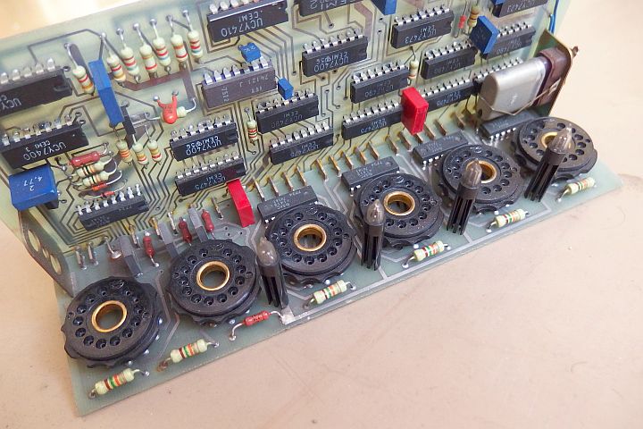
Choosing the nixie type:
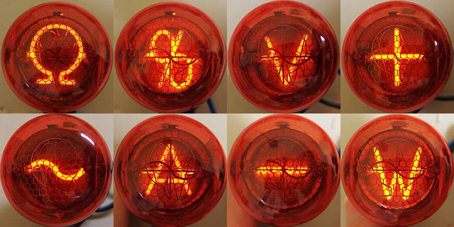
In the thermometer you can use almost any nixie for which there is a symbol type of similar shape and size containing the symbols "+" and "-".
The Soviet types IN-12A or IN-12B can be used with symbol tube IN-15A. Type IN-14 may be used with symbol tube IN-19V containing + and -.
In such case you can add IN-19A which contains a symbol °C, connected permanently, but it would only have an aesthetic function.
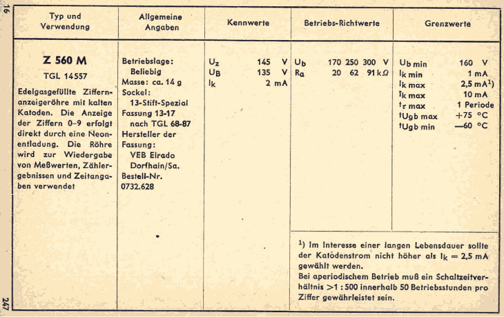
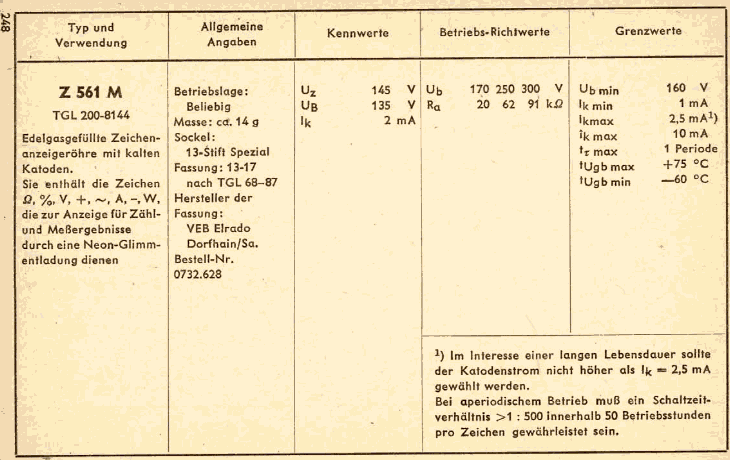
Of the RFT types you can use for example: Z560M with Z561M. Z566M with Z567M. Z5660M with Z5670M. Types Z570 / Z573M / Z574M with Z571M.
Types Z5700M / Z5730M / Z5740M with Z5710. Among Tesla types you can use ZM1040 with symbol tubes ZM1041 or ZM1041S. ZM1042 can be used e.g. with ZM1043 or ZM1043S.
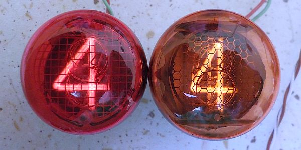
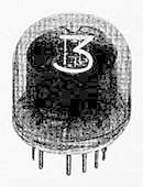
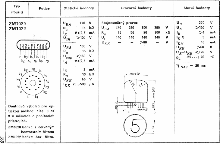
I do not know whether smaller Tesla nixies (eg. ZM1020 or ZM1080T) ever had a matching symbol tubes, but the type ZM1080T could combine with Z571M from RFT. Type ZM1020
can be combined with Z561M. For the last combination I decided.
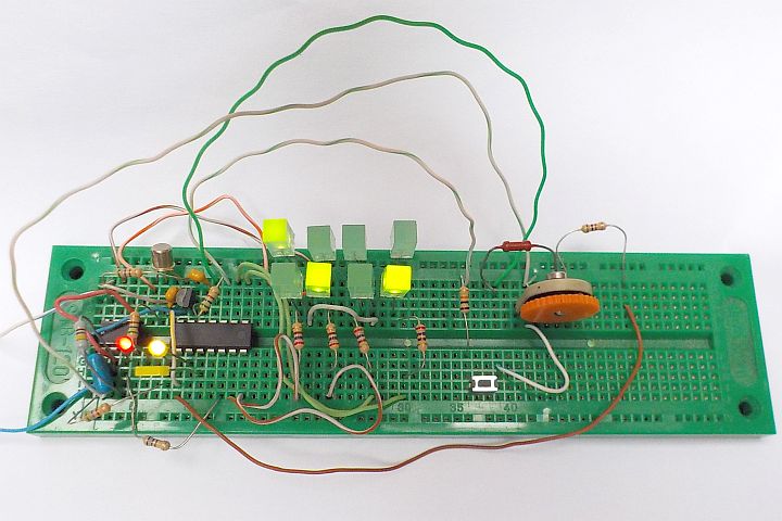
Circuit description:
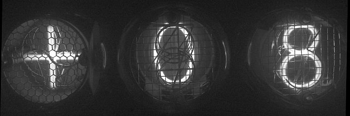
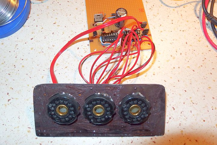
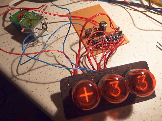
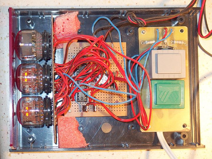
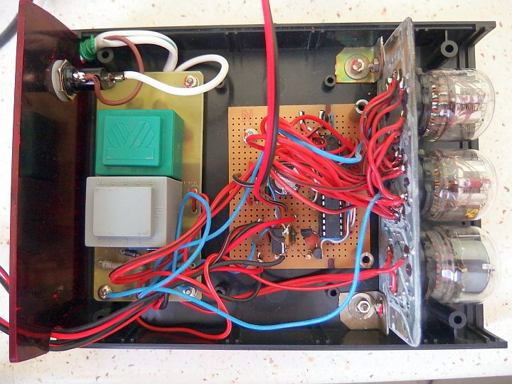
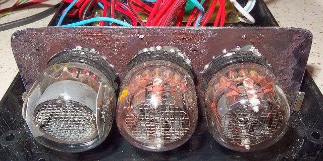
Nixie thermometer has a display consisting of two numeric and one symbol nixie tubes.
Numeric nixies E1, E2 are controlled by the so-called Mains duplex. It is a kind of a two-step multiplex
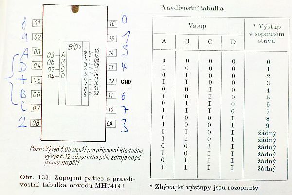
where one half cycle of mains illuminates one nixie and the other half cycle the other nixie. This allows you to use only one MH 74141 nixie driver.
Compared to the conventional multiplex there are also several advantages. It is not necessary to actively switch the anodes
(each anode would otherwise require two high voltage transistors).
Classical multiplex is also problematic because of the high rectangular waveform voltage that
induces a weak glow of inactive numbers (spirits) due to capacitive currents. In mains duples such a problem does not occur because it works with a sinusoidal voltage,
rather than rectangular. You can also omit filtering of the supply voltage, typical of classical multiplex. In addition, there are no capacitors charged to dangerous voltages,
which would be dangerous even when disconnected from the mains.
The symbol nixie tube E3 is controlled statically (no duplex) and switched using two high voltage transistors T2 and T3. They are rated at least 400V, better 500V.
You can use either N-MOSFETs or bipolar NPN transistors. For bipolar transistors, it is necessary to add a base series resistor.
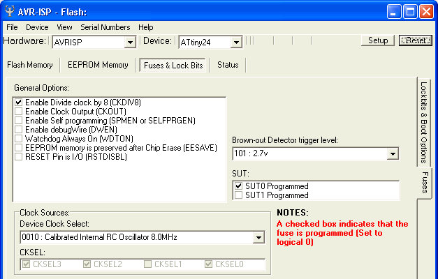
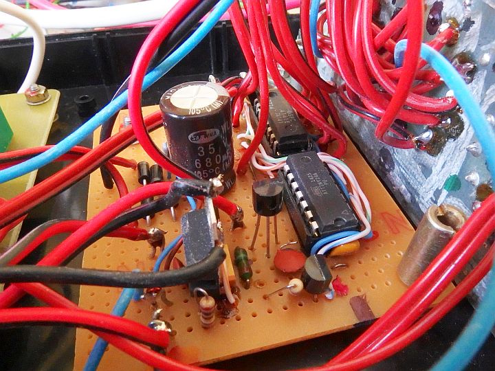
As a microcontroller I chose Atmel AVR ATtiny24A (ATtiny24, ATtiny24V). It provides all functions required for operation of the thermometer. Pin 5 (PB2 / INT0) is used
to synchronize duplex through shaping a transistor T1. If the duplex is swapped (the display swaps ones and dozens), then swap the primary or secondary
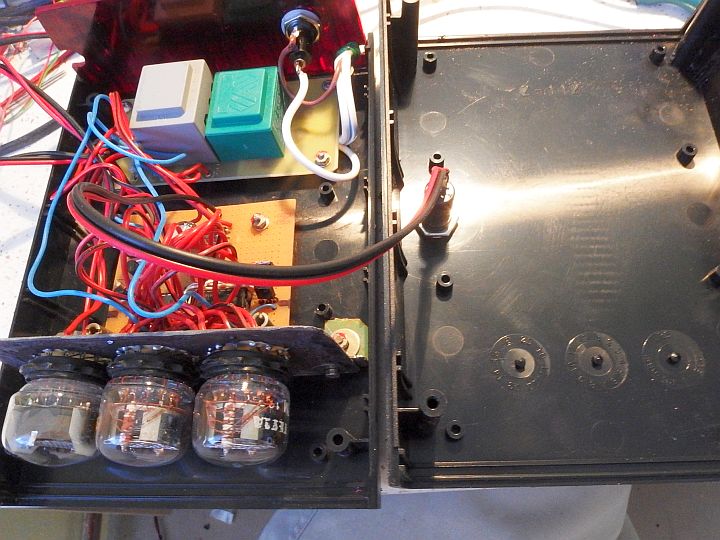
of transformer Tr2. The entire circuit is powered from the mains through a transformer Tr1 (230V / 9V about 1.5VA).
5V voltage stabilization traditionally provides circuit IO5 (7805). Thanks to the low consumption of logic it did not need a heatsink.
As the thermometer is connected to an external temperature probes, it must be electrically isolated from the mains for safety reasons.
Nixies therefore can not be powered directly from the mains without isolation, as in
nixie clocks with contained construction.
Because the transformers with a secondary voltage of hundreds of volts and low power (around 1-2 VA) are usually unavailable, I solved it differently.
Nixie anode voltage is obtained by using the transformer Tr2. It is reverse connected to the secondary Tr1 and thus transforms low voltage back to high voltage.
My first thought was to use two identical transformers (Tr1 and Tr2 would type 230V / 9V 1.5V). The output voltage should be theoretically 230V.
The problem is that small transformerd have considerable losses, and in practice the output voltage of such
two-transformer assembly is about 145V when idle and even less under load, which is not sufficient.
The second idea was to use a transformer 230 / 9V followed by a reversed transformer 230V / 6V to compensate the loss.
Here, however, another problem crops up. If you connect 9V to winding calculated for 6V, it leads to high saturation of Tr2 core and high inductive current,
that also overloads Tr1. Both transformers are then very hot and have high self-consumption.
It turns out that forcing a transformer with a 230V primary to operate reverse way (to provide 230V)
is much more problematic than it may seem. Small transformers have large losses compensated by adding turns to secondary and subtract turns
of the primary (the output voltage at idle is up to 60% higher). Therefore, when reversed, it always gives significantly less voltage than it theoretically should.
Moreover, if the output voltage corresponds to the original input voltage, the transformer operates at a higher induction and gets very hot.
A viable solution is to use a transformers with 400V primary. To the first transformer (230 / 9V 1.5V) I connected a
reversed transformer (400V / 9V 2.6V). The Tr2 transformer could be smaller, but the version with 400V primary and power less than 2.6VA probably doesn't exist.
This setup provides 270V at no-load and 210V when loaded, which is sufficient for nixies. In addition, the own consumption of the transformers is low
and they stay cool.
Each of nixies E1 and E2 is fed by one of half period of the output voltage Tr2, which also serves for their duplex. E3 symbol digitron
is powered by full-wave rectified voltage so that the power supply (Tr1 and Tr2) is loaded equally in both half periods.
Anode resistance of E3 is therefore twice the value so that the average current stays the same.
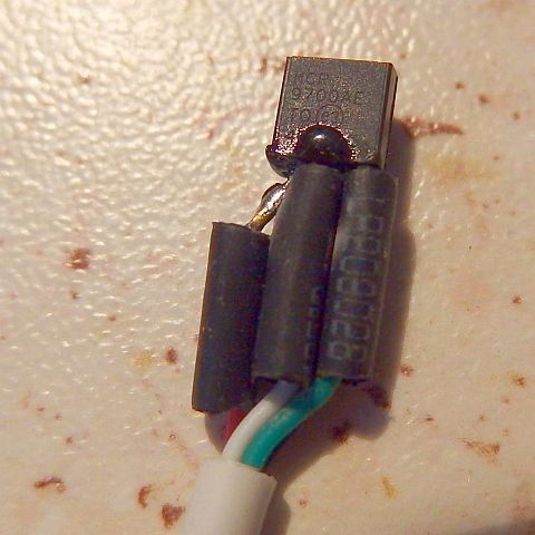
Indoor and outdoor temperature is measured by two temperature sensors IO1, IO2 - MCP9700A. They are connected to ADC1 and ADC2 inputs of the AVR .
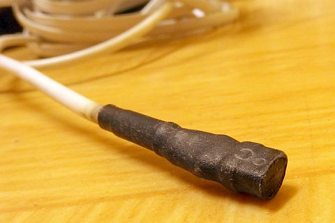
Outside temperature probe is on a long three-wire cable. Internal probe is on a short cable (20cm) outside of the case,
so that it is not influenced by the heat from the device.
Necessary accurate reference voltage (2.495V) is obtained by IO3 (TL431A) and applied to the input AREF.
The device is controlled by pressing TL1, used to recall or erase memory of the minimum and maximum temperature.
Nixie current is chosen low to extend their lifetime.
On the other hand, too small current can cause that the cathode lights up only partially.
When the pulsing current is used, the peak current value must exceed the minimum required value.
Resistors R1, R2, R3 determine the current to nixies.
If the current was not enough to display correctly, you can reduce resistance values of R1, R2 and R3.
Average current of nixies in this circuit is about 0.8 mA, which proved to be sufficient for correct display and for good readability even in daylight.
The power consumption of this thermometer is cca 1.9W.
Reading and using the thermometer:
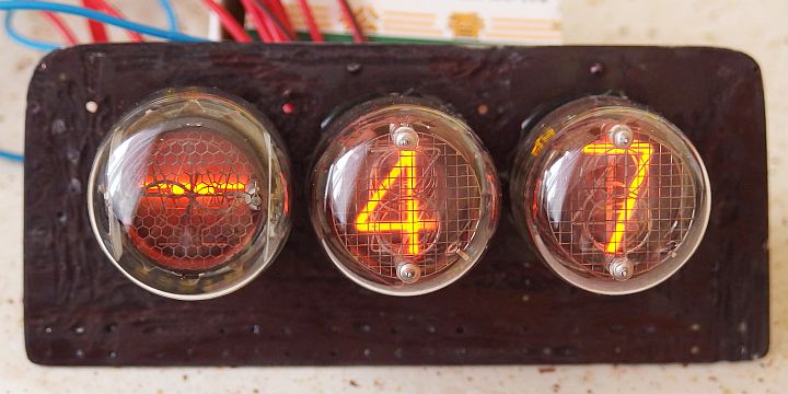
Thermometer always displayes external temperature for 2 seconds, internal temperature for 2 seconds and finally rotates all digits
for 0.4 seconds (for prevention of cathode poisoning).
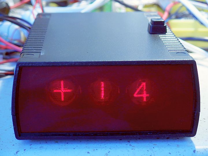
Outside temperature is displayed with a "+" or "-" sign. The internal temperature is displayed without a sign (it is'nt expected to be ever negative).
This also helps to distinguish between each displayed data. TL1 button can recall memory for minimum and maximum.
By pressing the button the nixie thermometer displays first the OUT minimum, then OUT maximum, IN minimum and finally IN maximum.
After 4s it will return to actual internal and external temperature display.
Long press (at least 2s) of button will reset the memory of maximum and minimum.
Rotation of numbers (slot machine) is needed because in the thermometer, the display does not change too often, and the numbers are not used uniformly.
Without this, a cathode, which does not illuminate for long time becomes covered by material sputtered from illuminating cathodes,
and later wouldn't work properly (it would suffer cathode poisoning). Especially figure of dozens changes only rarely according to season changes.
Rotation function always quickly lights up all the numbers from 00 to 99, thus preventing the poisoning.
At the same time, symbol nixie E3 momentarily shows the opposite sign than the one that is being displayed together with OUT temperature.
Without this, for example, after 3/4 year of continuous operation of "+" sign the "-" wouldn't work at all.
Long term operation experiences:
24. 10. 2015 - Continuous operation of the nixie thermometer started.
28. 6. 2019 - 3 years 8 months of operation with no failure, no signs of nixie wear.
The program for free download:
Source code in assembler (ASM)
Compiled HEX file (822 Bytes)
How to write the program into the AVR is described here.