Introduction:
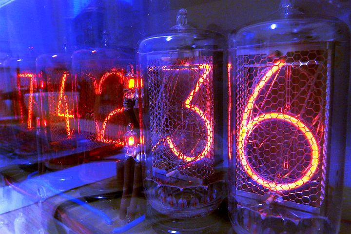
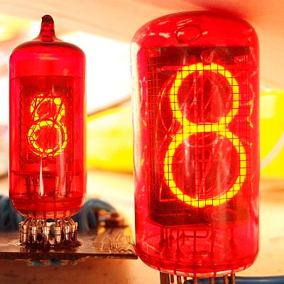
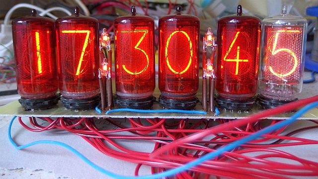
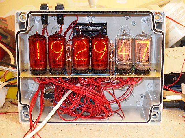
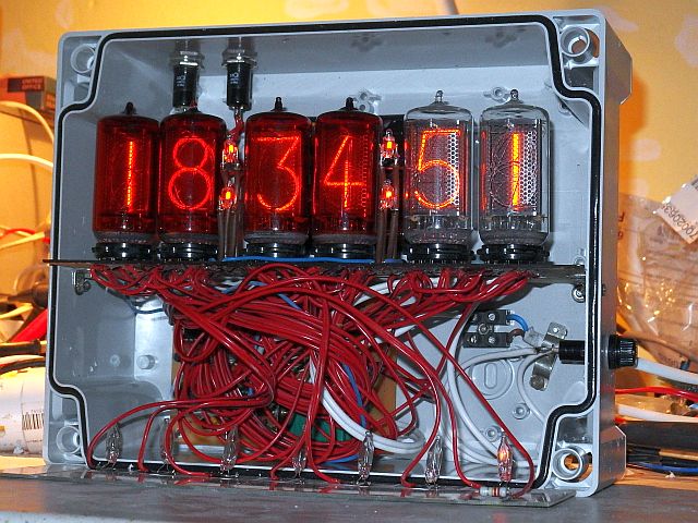
I decided to build my third nixie clock. This time I wanted to use some bigger tubes (about 30 mm character height)
with side view (they look more like traditional vacuum tubes). Big tubes are good as they tend to be installed into socket rather then soldered.
What nixie tubes are I describe here in detail.
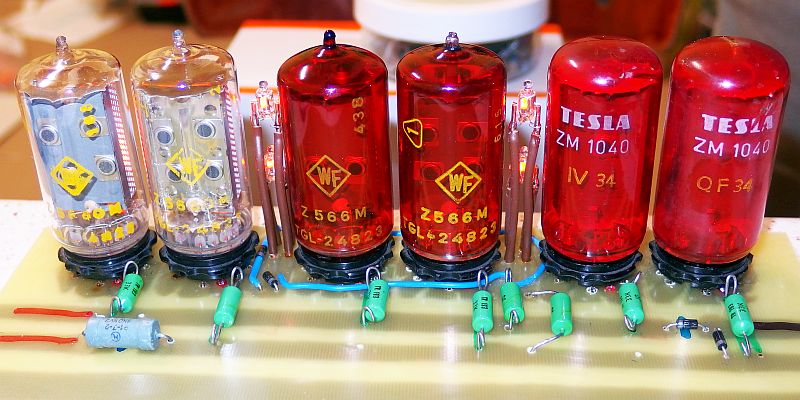
Choice of nixie type:
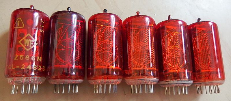
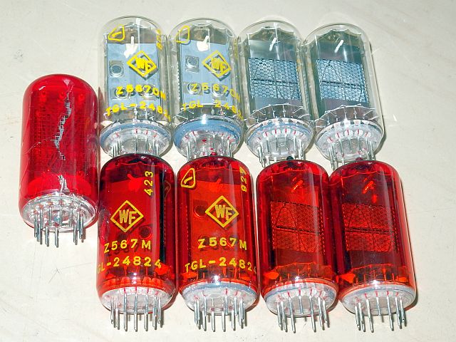
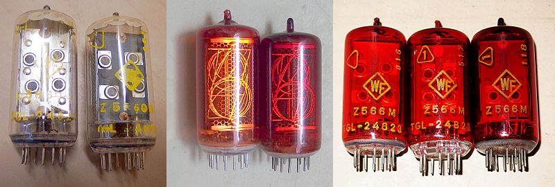
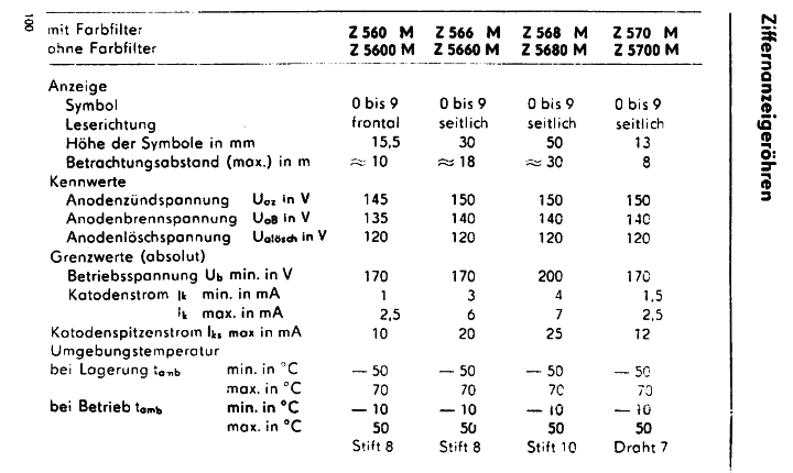
Nixies, which fulfill these requirements and can be found in my country, are particularly Z566M and its variant without paint Z5660M from the East German RFT and
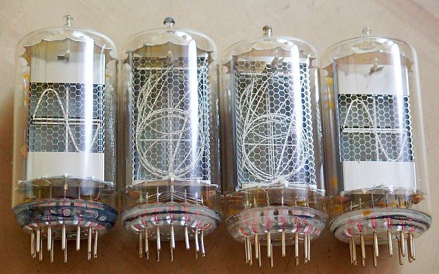
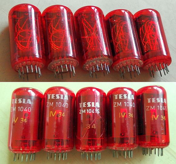
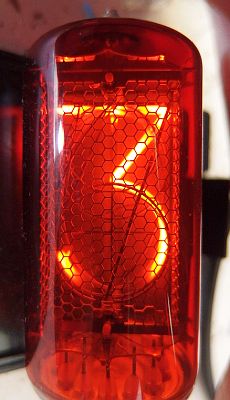
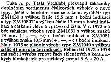
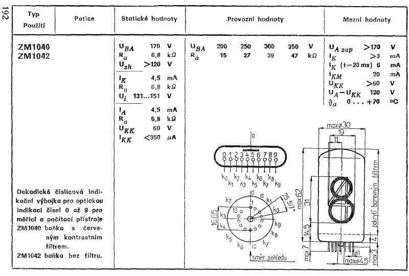
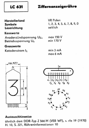
the ZM1040 (and ZM1042 - its version without paint) from Czechoslovak Tesla, or even LC-631 from the Polish Dolam. All of these types have a digit about 30-31 mm high.
The Z522 and Z5220M also look interesting, but it is an older type made in the west, and therefore hard to come by. Soviet Union
contributed to the world of nixies with a very interesting piece IN-18 (ИН-18) with a respectable 40 mm character height.
Although Czechoslovakia imported a lot of things from USSR during socialism,
IN-18 can't be found here. Interesting, but also quite hard to come by, is Z568M or Z5680M from RTF with a digit height of 50mm.
So huge nixie probably didn't have wide use and only a little of them was made. Then there are some western European and American models with
50-60 mm high numbers, for example NL-7037, or totally insane Japanese nixie CD47 GR-411 and CD47 GR-414 with a whopping 135 mm high numbers,
but there's absolutely no chance to find such miracles of the capitalist world in the Czech Republic, Slovakia or anywhere in Central Europe.
Getting the nixies:
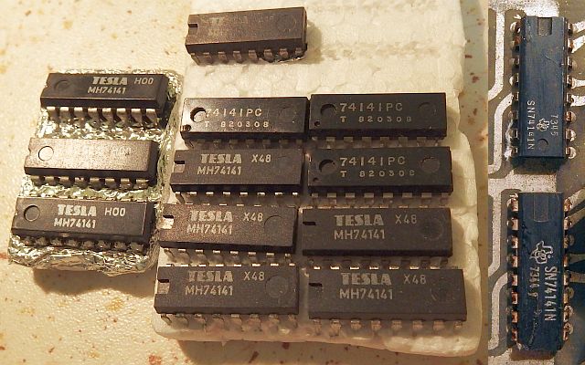
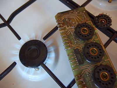
As easiest to find eventually proved Z566M from the East German RFT, ZM1040 from Czechoslovak Tesla and the Z5660M,
which is actually a colorless mutation Z566M and can, if necessary, be made from Z566M by removing the paint :).
The ZM1042 can be made from ZM1040 the same way. Nixies with 3cm high digits are probably the largest that were used widely, for example in desktop
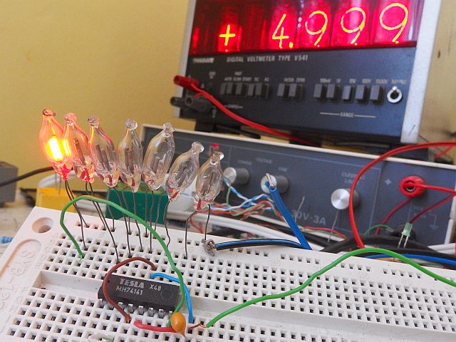
counters, voltmeters, multimeters and industrial automation. Z566M can be found for example in Polish voltmeter
Meratronik V541 and others.
ZM1040 are in similar devices from Tesla.
I wanted to keep all of my new Z566M and Z5660M in their original retail boxes. I also wanted my
functional Meratronik V541 to stay complete. So I decided to use some used tubes.
Originally I thought about used Z5660M which at time I unfortunately had only
2 pieces. I had only 5 pieces of ZM1040. Unfortunately, most desktop multimeters had right 5 nixies.
Thus I used the easiest to get Z566M nixies from heaps of broken Meratronik voltmeters - series V530 and V540. Those nixies might also be
unpainted to be mixed with Z5660M if necessary.
Another option was ZM1040, but the 6th piece and 2 spares I found too late.
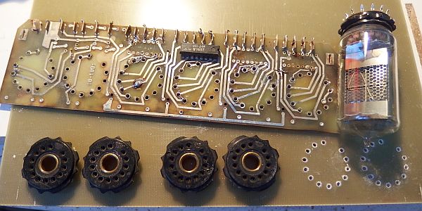
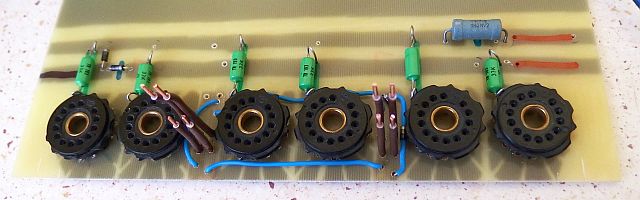
Choice of the separators:
Besides nixies, also separators must be chosen for separation of each pair of numbers.
No available big nixie has internal decimal point, so it is necessary to use external separators.
The original idea was to use other nixies as sepatarors, namely symbol types that display symbols as e.g. "+", "-" or "~".
These types include symbol nixie tubes Z567M (for Z566M) or Z5670M (for Z5660M),
ZM1041, ZM1041S or ZM1047 (for ZM1040) or ZM1043 and ZM1043S (for ZM1042).
Symbol tubes have the same base and glass bulb as the numeric tubes to which they belong. Therefore, their use as delimiters seems aesthetical.
On the other hand it increases the dimensions of the clock, complexity and power consumption.
In addition, use of more components that are no longer produced, may complicate future
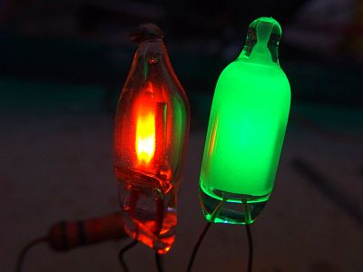
maintenance. That's why I decided to use neon lamps as delimiters. If the clock has date display, the use of glow lamps also contribute
to better readability. Glow lamps can form a colon, which at first glance separates hours, minutes and seconds. If only the lower lamp of the colon is on,
at first glance it is clear that the date is displayed. Telling date from time when using + - ~ symbols would be quite confusing.
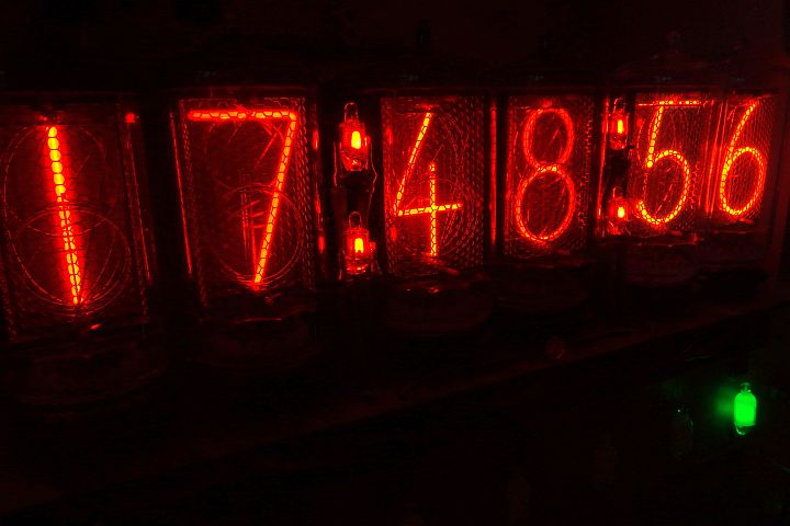
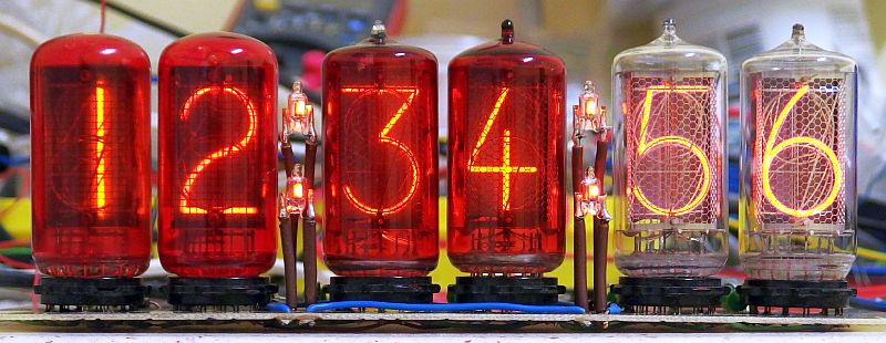
Nixie clock features:
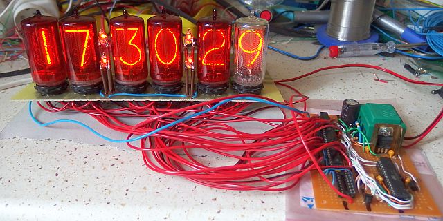
A clock obviously has to show time :). In case of clock with large nixies it must include seconds,
otherwise the beauty of big changing digits does not stand out.
It also shows the date and day of the week. It can count leap years and automatically move to summer and winter time.
There is also an alarm clock with a choice of single, weekdays or every day. It also has a digital correction of run speed.
Operating hours counter is useful for monitoring the durability of nixies. At regular intervals,
is rotates all the digits (slot machine) in order to prevent cathode poisoning of the nixies.
You can also manually turn on a permanent rotation for nixie regeneration.
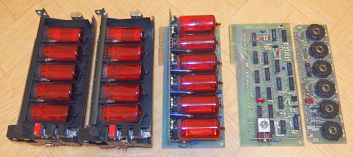
The functionality is based on previous Nixie clock. They are more or less identical except the
day of the week display. In previous clock it was displayed with the number (1-7) together with date. In this clock
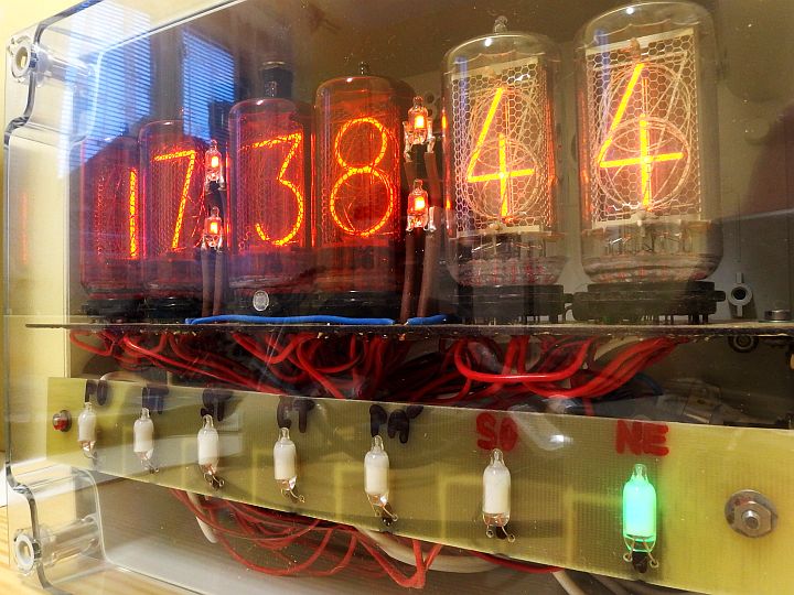
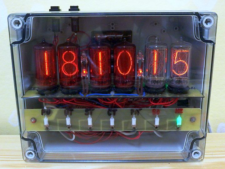
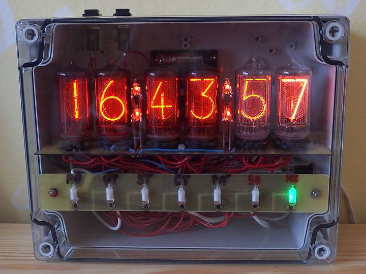
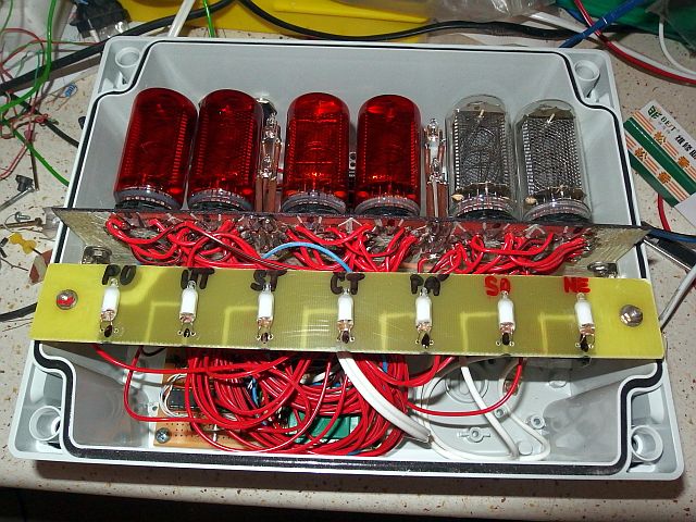
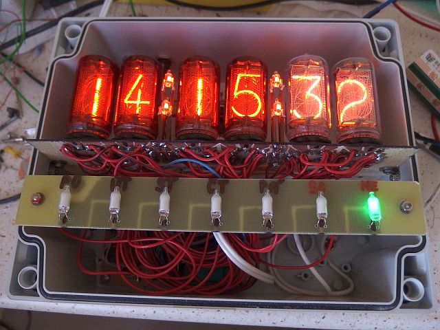
the day of the week is indicated through seven large green neon lamps (type NEON-9) and the last pair of nixies shows a year (the last two digits).
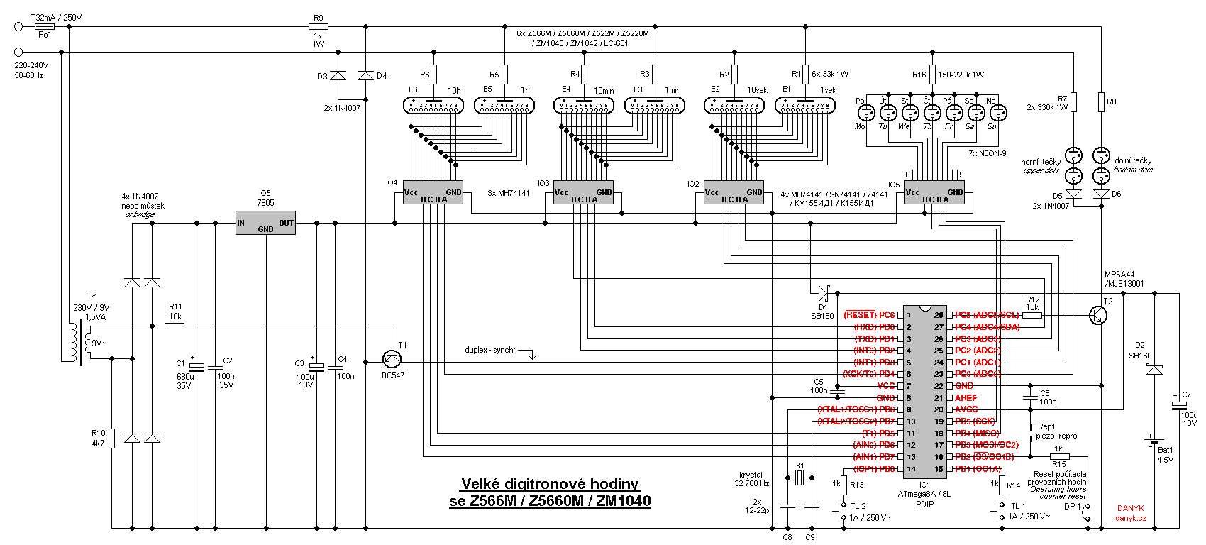
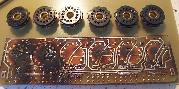
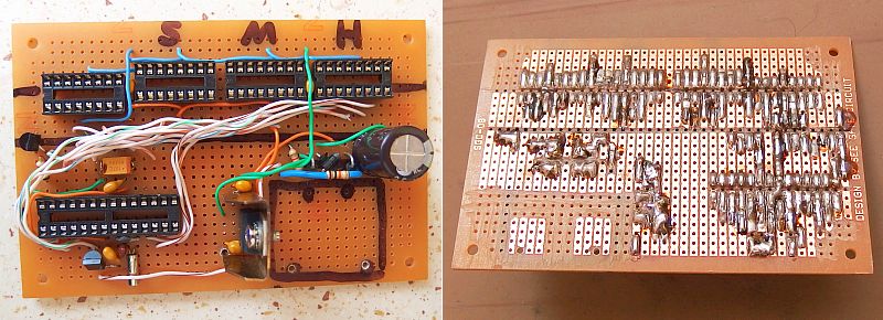
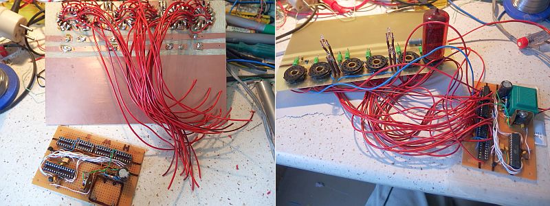
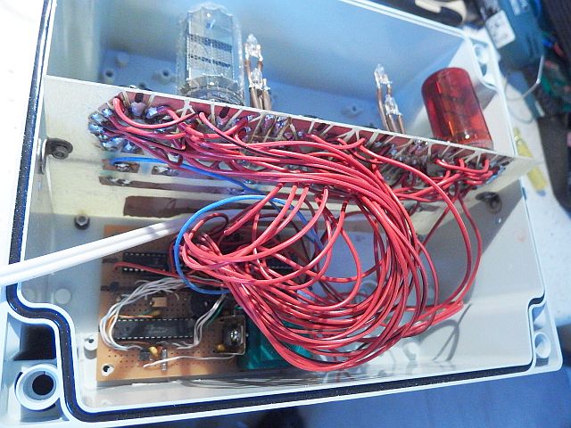
Schematic description:
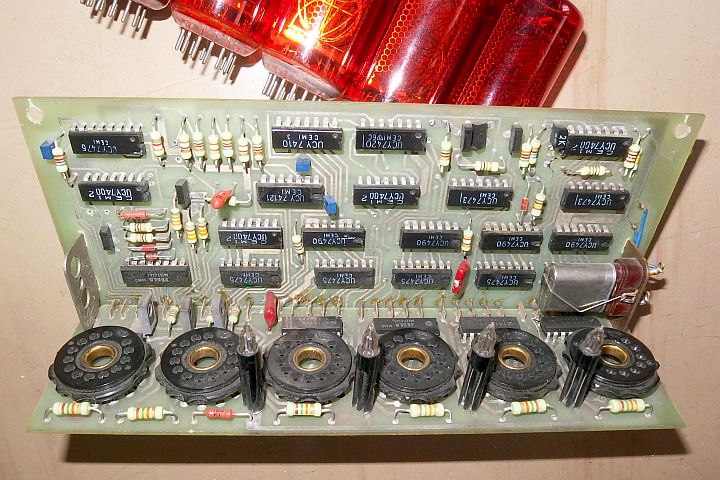
The clock has six digit display composed of nixies. Nixies are controlled in so called duplex. It is the equivalent of a two-step multiplex
wherein one half cycle of mains illuminates one half of nixies (3) and the other halfcycle the other 3 nixies. In this case, the display is divided into
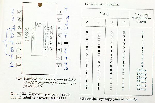
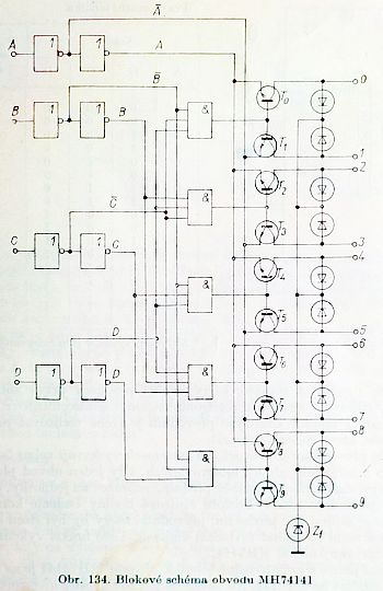
even and odd positions. The advantage of this drive system is that, compared to static drive, it reduces the number of nixie drivers (MH 74141) from six to three.
Compared to the conventional multiplex there are also several advantages. It is not necessary to actively switche anodes
(each anode would have to have two high voltage transistors) and it does not require such a large pulse current to achieve
desired brightness, compared to 6-step multiplex. Classical multiplex is also problematic because the large voltage with rectangular waveform causes
ghosting because of stray capacitances. For a duplex system, such problem does not occur because it works with a sinusoidal voltage,
rather than rectangular. You also don't have to filter the anode voltage, as in classical multiplex, and there are absolutely no capacitors charged to dangerous voltages.
Mains duplex also eliminates nixie singing (mechanical resonance), which can occur when large nixies are multiplexed.
It should also be noted that in vingate machines multiplex was only used with small nixies.
For large nixies (over 18 mm) no multiplex was originally used and the datasheet usually does not allow it.
Mains duplex supplies the nixie with the same waveform as classic half wave rectifier without a capacitor, and thus it complies with the datasheet.
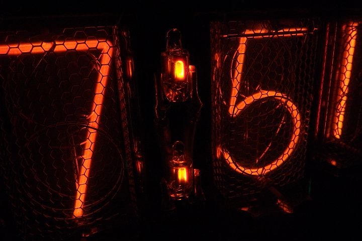
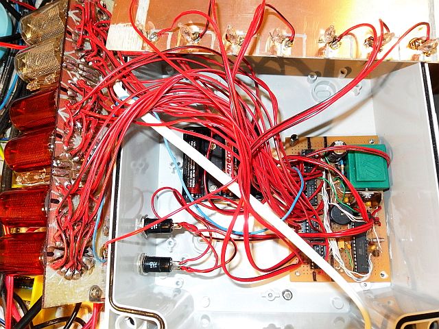
As delimiters, two colons are used, made of miniature neon glow lamps. They are divided into two pairs connected in series.
One pair consists of upper dots, the other of bottom dots. This lets you use the bottom dots as dots for date. Both groups of glow lamps are also connected to the duplex,
so just a single HV transistor (T2) is needed.
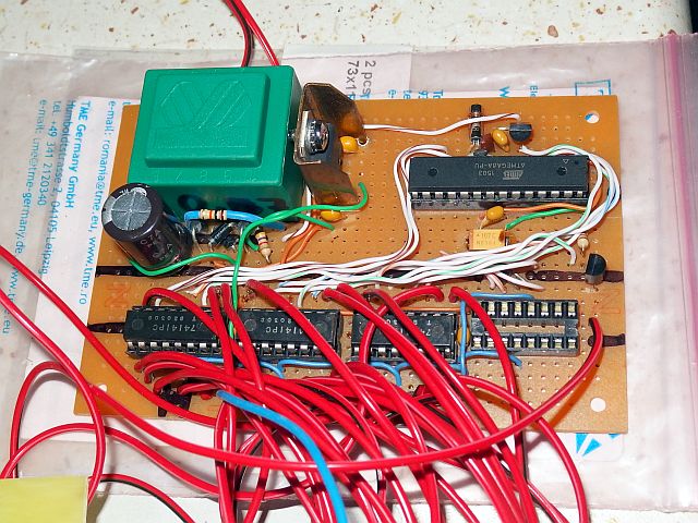
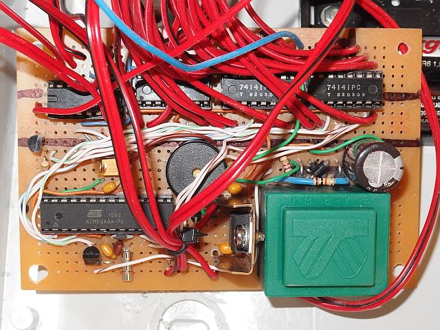
As a microcontroller I chose Atmel AVR ATmega8A (ATmega8L). It provides all functions required for clock operation. PD3 pin (INT1) is used
to synchronize duplex over a transistor T1. If the duplex is inverted (the ones and tens are inverted) swap the polarity of primary or secondary of the
auxiliary transformer Tr1. Tr1 transformer (230V / 9V, about 1.5VA) is used as a supply for logic, but also to sense the half-cycles for duplex sync.
5V voltage regulation is traditionally done by IO5 (7805) with a tiny heatsink. To avoid resetting the clock during power outages, it is not lacking
backup battery. It has a voltage of 4.5V (possibly 3V, 3.6V or 3.7V). I used three AA cells. You can use much smaller batteries because the
consumption during backup is only about 9uA. During battery operation, the nixies are not lit of course, and the power only goes to
the microcontroller, not to the hungry 74141, that draw up to 32 mA each, according to catalog (I measured 24 mA).
Backflow current from the battery to the drivers 74141 and to 7805 is prevented by Schottky diode D1. The diode D2 prevents unwanted battery charging
during mains operation.
Piezo speaker Rep 1 is used to produce the alarm sound. It can be replaced it with an induction speaker with cca 1uF capacitor in series.
Alarm works even when operating on battery power. The clock is controlled using buttons TL1 and TL2.
PD3 pin (INT1) is used to synchronize the duplex and sense whether the mains voltage is present.
When there's no level change for 250ms, battery operation is detected and
the clock enters power saving mode. Outputs of microcontroller leading to 74141 drivers (and T2 base) are set to 0 during this condition.
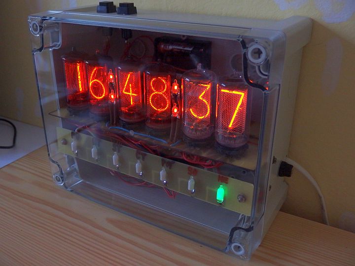
The Nixie Clock is powered from the mains without isolation, because mains voltage of 220 - 240V is about the most appropriate voltage to power nixies.
Operation without isolating transfomátoru is possible if the clock is enclosed in a suitable safe box and no live part is
externally accessible. The backup battery must be inside and inaccessible from the outside (don't use battery holder with a door).
The buttons must be rated for 250V AC as not only the contact-contact voltage is essential, but also the "contact-man" voltage :).
Nixies obviously are not exposed, they are safe under a transparent cover. Construction with uncovered nixies is in my opinion not only
dangerous (even in case of mains isolation or DC/DC inverter), insane, but also quite prone to nixie mechanical damage and finally totally anachronistic
(I do not know about any original device with exposed nixies). It is of course possible
to use isolation transformer. For 100-120V mains, use 1:2 transformar (120 to 240V) or autotransformer.
For example, a primary of a dual voltage transformer can also be used as autotransformer. Even the 120V : 120V isolation transformer
can be wired as 120V : 240V autotransformer. But keep in mind that autotransformer does not provide mains isolation.
Clock without mains isolation transformer obviously can not be connected to the programming interface.
Programming the MCU can be done outside the board or running on the backup battery.
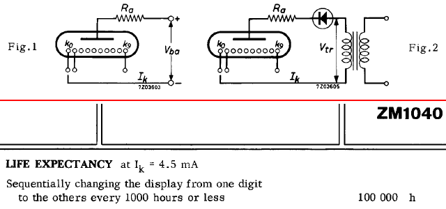
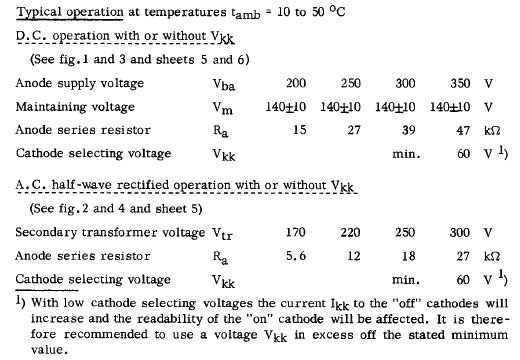
Nixie current is chosen as small as possible to extend their lifetime. Datasheet gives the DC current min. 3mA, max. 6 mA. Recommended value is 4.5 mA.
Too small current can cause partial cathode glow.
When using the pulsed current, the peak value must exceed the minimum nixie current.
Resistors R1 - R6 define nixie current. Resistor R9 is used to fine tune the current and can be deleted.
Nixie voltage drop is usually about 140V and the peak voltage of 230V mains is 325V, so the peak resistor voltage is therefore 185V.
The resistors are chosen so that the peak current will reach about the recommended current value. R = U R peak(185V) / I peak.
If the power was not enough for the nixies to display correctly, you can reduce resistor values.
I set the peak current to approximately 5.1 mA (average current is approximately 1.2 mA). It turned out that it is enough for the nixies to display correctly
and to reach good brightness and readability even in broad daylight. The total power consumption of the clock is cca 3.9W.
Program:
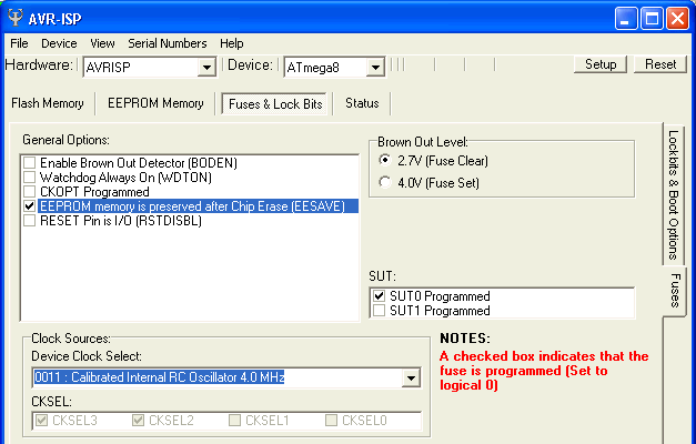
The program for the nixie clock is available below for download in the HEX file (directly for microcontroller) or as
source code in assembly (ASM) for possible modifications. You can see microcontroller configuration bits setting in printscreen below. It shows
both AVRISP and PonyProg setting window. The clock is controlled by a low frequency crystal (32 768 Hz), which enables low power consumption when
running on a battery. MCU is clocked at 4MHz from the internal RC oscillator. AVR goes into Idle sleep mode when inactive during mains
operation. When battery powered, it uses Power Save mode, enabling very low power consumption. CPU clock is off in this condition and
only asynchronous timer/counter2 is running. The Nixie clock has an Operating hours counter. To avoid data loss while disconnected
from both mains and battery, the 24bit data are stored in EEPROM and updated 8 times per hour. To avoid early EEPROM wear (guaranteed lifetime of each
Byte is 100 000 writes) wear levelling is used. The lowest byte storage is rotated between 96 different bytes in EEPROM. For higher
two bytes it is not necessary because the update only occurs on low byte overflow, which is 256x less often. 100 000 writes in any particular
byte won't therefore occur before 137 years of continuous operation! Crystal compensation byte is also stored in EEPROM. Date and time
display cycle repeats every 7 seconds. The number 7 was chosen because it is relatively prime with the numbers 10 and 60, and thus
there is no uneven wear of nixie cathodes of seconds when displaying the time. Time is displayed for 5 seconds and date for only 2
seconds, because the time is more volatile and therefore more friendly for nixies.
Setting and using the Nixie Clock:
The clock is controlled by TL1 and TL2 buttons.
• 1. Time/date display
The clock has two basic modes of display. The first one shows only the time in the form "HH:MM:SS" (Hours:Minutes:Seconds).
The second mode alternates the time and date with a period of 7 seconds. Time is always displayed for 5 seconds and date for 2 seconds.
Date is displayed as "DD.MM.YY" (Day.Month.Year).
Between these two modes you can switch by pressing TL1. In both modes digits are rotated (slot machine) for 1.25 seconds every 49 seconds.
The day of the week is indicated by one of 7 neon lamps at all times.
• 2. Alarm clock
The nixie clock has an alarm. Button TL2 gradually switching between displaying the time display, date-time display and the four-step alarm settings:
Alarm hours, alarm tens of minutes, alarm minutes and alarm mode. The setting is done using
TL1 button. Alarm modes are: 0 - disabled, 1 - once, 5 - five working weekdays, 7 - every day.
Alarm setting is indicated by alternately flashing dots. Alarm beeping can be stopped by any of the buttons.
• 3. Setting the clock
Long pressing of TL2 button gets you into the process of setting the clock. You set hours, then tens of minutes, minutes, seconds, day of the week,
day, month, year and finally the automatic DST (daylight saving time / summer time) shift (111111 = on, 000000 = off).
The setting is done using TL1, you switch between the steps using TL2. After four minutes of inactivity, the clock
automatically returns from settings to the time + date display (this protects nixies from static display wear).
• 4. Automatic DST
If the automatic DST is enabled, the move to summer time takes place on the last Sunday in March. 1:59:59 is followed by 3:00:00.
Move to winter time takes place on the last Sunday in October, 2:59:59 is followed by 2:00:00.
(According to the rules valid in almost all European countries including the Czech Republic and Slovakia since 1996)
• 5. Special features
Long pressing of TL1 get you into special features. The first one is nixie test in which
all nixies run numbers from 0 to 9, changing every 1s. It can also be used for nixie maintenance (against cathodes poisoning).
Another press of TL2 will take you to another special feature, which is the compensation of the crystal. If the clock is not accurate,
you can adjust it in the range of -75 to +75 ppm with 3ppm (3 millionths) steps. Use TL1 button to set the value.
Negative values are displayed on the left, positive on the right (eg. -12 ppm displays as "12 00 00" and + 75ppm as "00 00 75").
After pressing TL2 you get to the last special feature, which is the operating hours counter.
It displays total clock and nixie tube operation time (in hours). The following press TL2 longer takes you back to the time display.
Operating hours counter can be reset by connecting a jumper wire DP1 and long press of both TL1 and TL2 buttons
simultaneously. The dots will flash quickly and the counter is reset to 000000. Resetting is recommended only when you change nixies.
Under normal circumstances it is recommended not to connect the DP1 jumper.
Long term operation experience:
28. 6. 2019 - 22 500 hours of operation. No failure, no signs of nixie wear.
The program for free download:
Source code in assembler (ASM)
Compiled HEX file (2 920 Bytes)
How to write the program into the AVR is described here.