Intro:
After 22 years of being interested in DIY electronics, I finally decided to build what everyone shoud once build - a Nixie Clock.
What the nixies are I describe in more detail in this article.
Clock functions:
Of course, the clock displays the time. Including seconds, because without moving seconds
with figures jumping to different depths of the nixie, it is simply not the proper nixie clock.
It also shows the date and day of week. It can count leap years and automatically switch to daylight saving time (DST) and back.
There is also an alarm clock with single time alarm, weekdays alarm or every day alarm. I also implemented software correction of crystal and
operating hours counter, which is very helpful for monitoring of nixie lifetime. At regular intervals,
the slot machine effect (number flipping) is done to prevent cathode poisoning. You can also manually turn on a permanent slot machine for nixie regenerating.
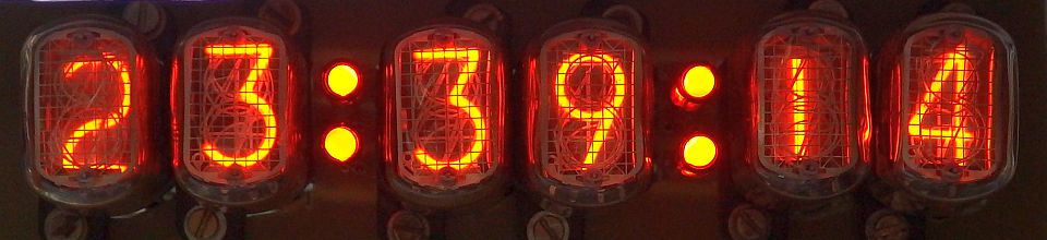
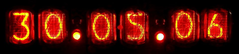
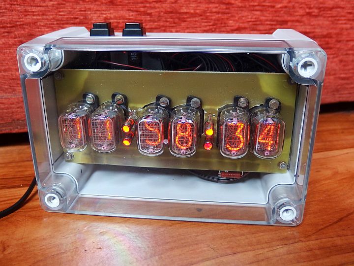
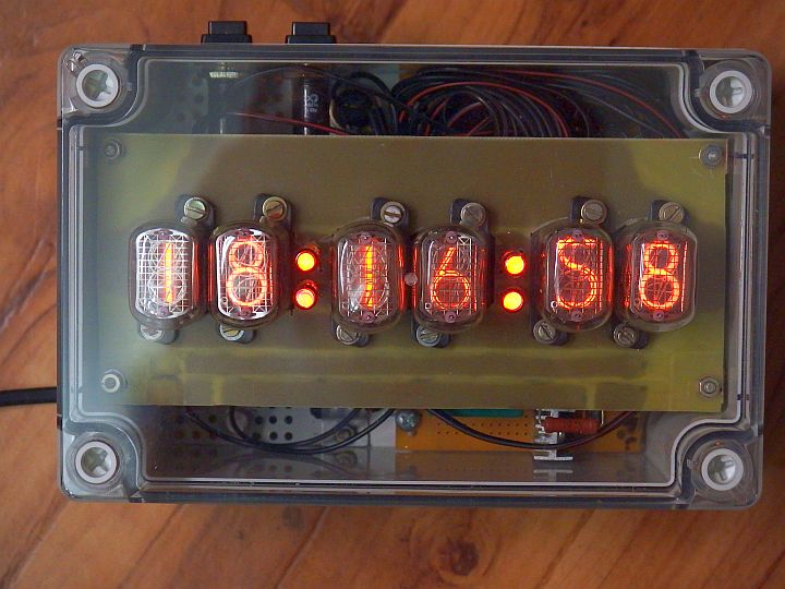
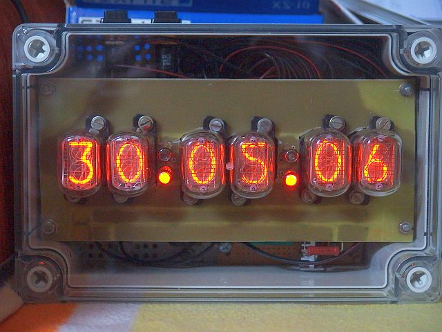
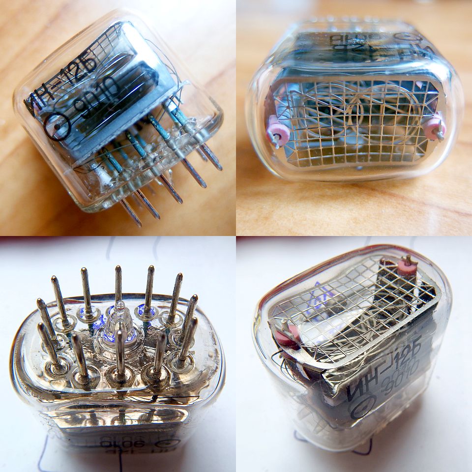
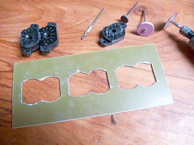
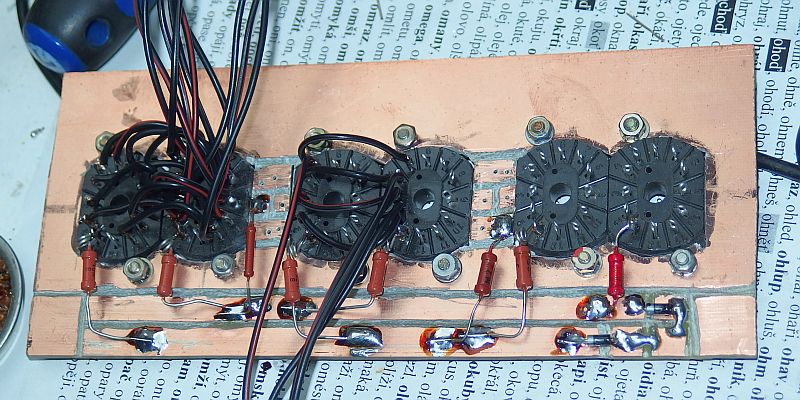
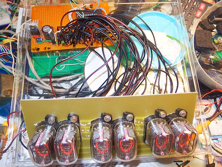
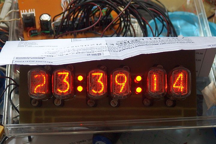
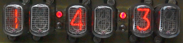
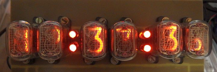
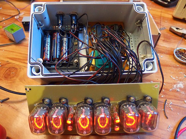
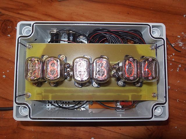
As a display I used six IN-12B nixies (character height 18 mm) and as dots I used neon lapms INS-1 designed for DC current operation.
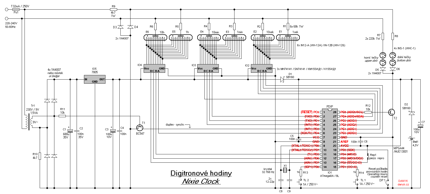
Circuit:
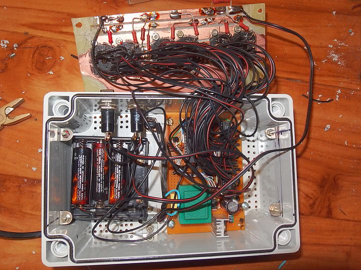
The clock has a display made up of six IN-12B nixies. You can also use IN-12A with no modification. They differ only by the absence of
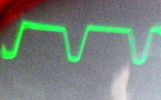
decimal point, which is not used here. Nixies are controlled by so called mains duplex. It's similar to the two-step multiplex
where one half wave of mains illuminates one group of digits and the other half wave illuminates the other group. In this case the display is divided into
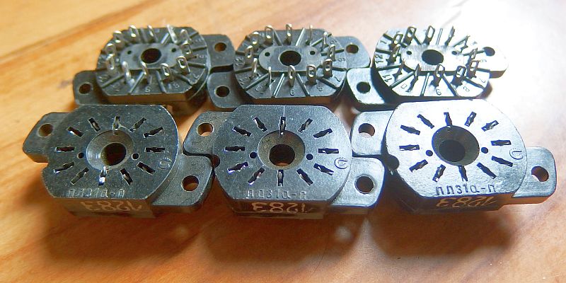
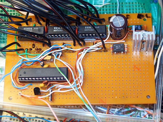
even and odd positions. The advantage of this circuit is that it, compared to static drive, it decreases the number of nixie drivers (74141) from six to three.
Compared to the conventional multiplex there are also several advantages. It is not necessary to actively switch the anodes
(two HV transistors for every anode). It also does not require as large pulse current to achieve
desired brightness, compared to six step multiplex.
Classic multiplex is also problematic because of the high rectangular waveform voltage that
causes a dim glow of inactive digits (ghosting) because of capacitive currents.
In a duplex such a problem does not occur because it works with a sinusoidal voltage,
rather than rectangular. You also don't have to care about smooth supply voltage, typical of classical multiplex. There are absolutely
no capacitors charged to dangerous voltages.
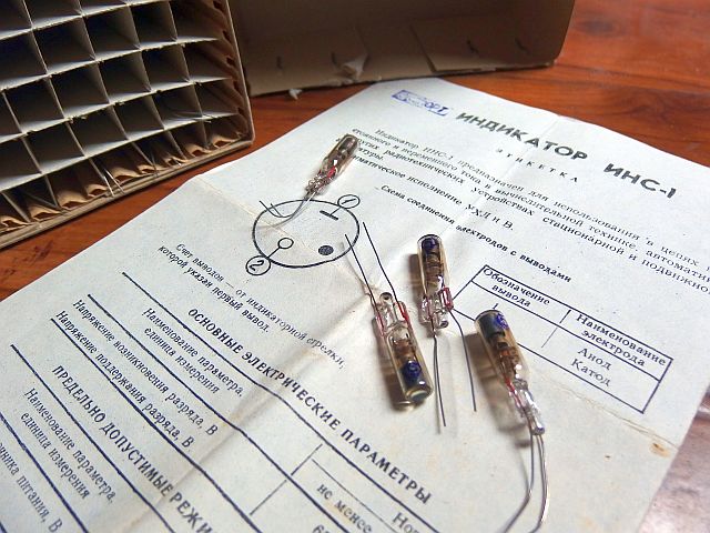
The separators are two colons formed by two pairs of neon glow lamps INS-1. They are divided into two pairs connected in series.
One consists of upper dots, the second one of bottom dots. This allows you use the bottom dots as dots for date. Both groups of glow lamps are also combined into a duplex,
so that they can all be driven by a single HV transistor (T2).
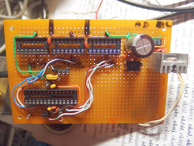
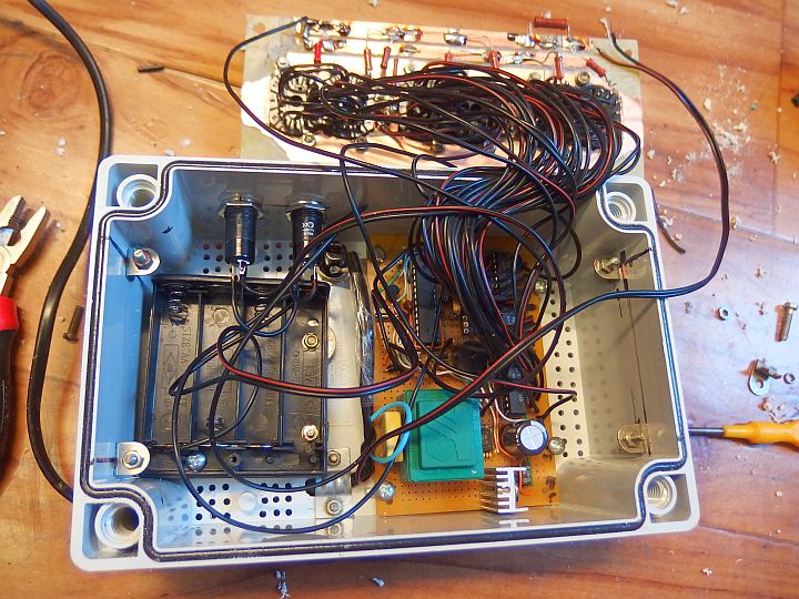
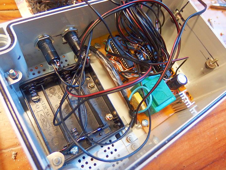
As a control circuit for my nixie clock I chose Atmel AVR ATmega8A (ATmega8L). It provides all functions required for clock. PD3 pin (INT1) is used for
synchronization of duplex via the transistor T1. If the duplex is reversed (ones and tens are swapped), reverse the primary or secondary of
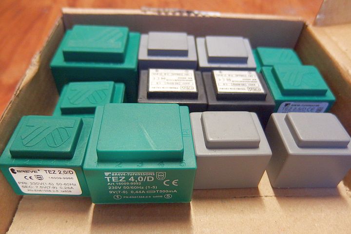
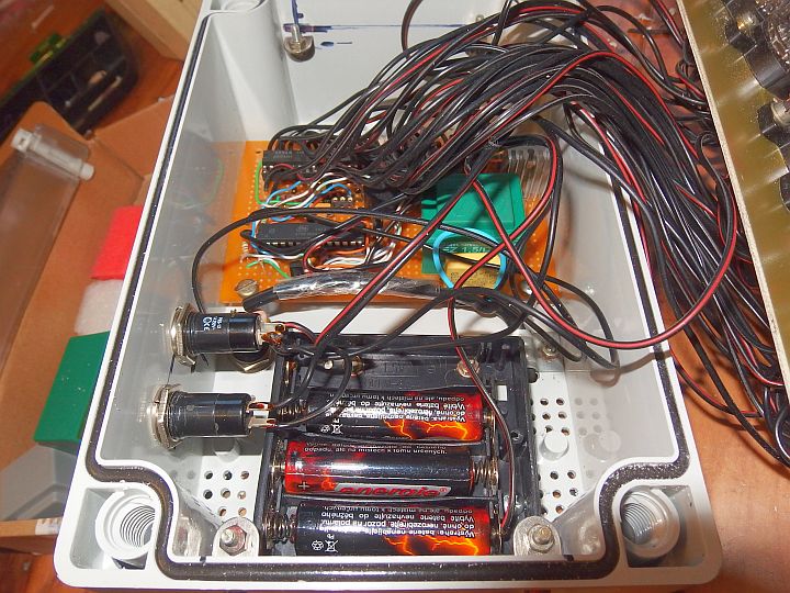
auxiliary transformer TR1. The transformer TR1 (230V / 9V 1.5VA) is used as a supply for logic, but also to sense the half-cycles.
5V stabilized voltage is traditionally provided by IO5 (7805) with a small heatsink. To avoid resetting the clock during power outages, they are not lacking a
battery backup. It has a voltage of 4.5V (or 3V, 3.6V or 3.7V). I used three AA cells. A much smaller battery would be enough, because
consumption during backup is only about 9uA. During battery operation the nixies are of course not lit and so only
IO1 is operated, not the power hungry 74141. Their self consumption is, according to the catalog, up to 32 mA (I measured 24 mA).
Reversed current from the battery into the 74141 drivers and into the 7805 is prevented by Schottky diode D1. The diode D2 prevents unwanted battery charging
during mains operation.
Piezo beeper Rep1 provides audible signal (alarm). It can be replaced with an induction speaker with about 1uF capacitor in series.
Alarm works even when on battery power. The nixie clock is set using the TL1 and TL2 buttons.
Pin PD3 (INT1) is used to synchronize the duplex and to detect whether the mains voltage is present. If there is
no change in the level for 250ms, the clock switches to battery operation. Outputs of IO1 leading to the 74141 drivers and T2 are set to log 0.
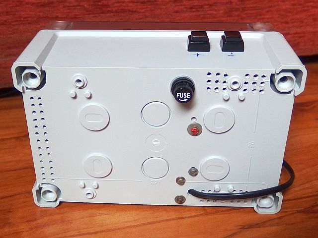
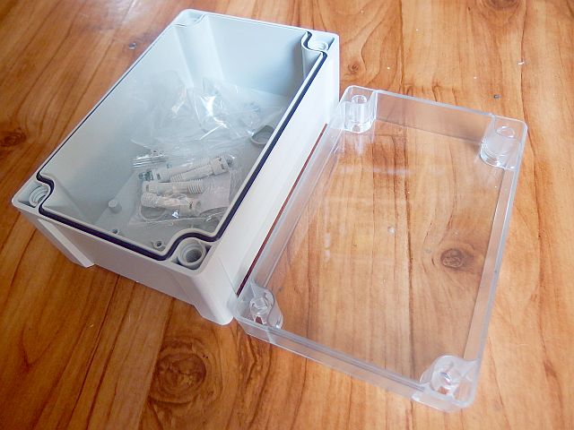
Nixie clock is powered from the mains without isolation. Mains voltage of 220 - 240V is about the most appropriate voltage to power the nixies.
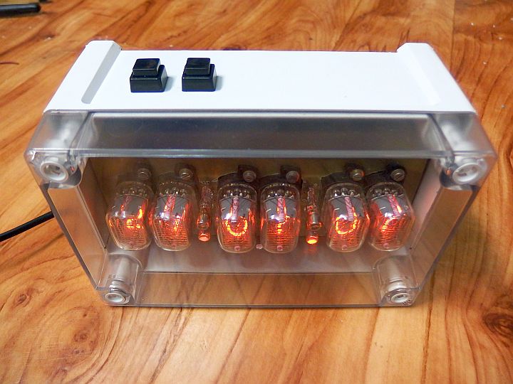
Operation without isolating transfomator is possible if the clock is sealed in a suitable safe box and no live part are not
externally accessible. The backup battery must be closed and inaccessible from outside (do not use housing for the battery with a door).
The buttons must be rated for 250Vac, because it's not just a about contact-contact voltage, but also about contact-human voltage.
Nixies are obviously not exposed, they are safely placed under a transparent cover. Construction with exposed nixies is in my opinion not only
dangerous (even in case of power supply isolated from mains), but also quite prone to mechanical nixie damage and ultimately great anachronism
(I do not know of any device from the times of normal use of nixies, which had nixies uncovered!). It is of course possible
to construct the nixie clock with isolation transformer (or with a 100-120V / 220-240V transformer
for the 100-120V countries). Nixie clock without mains isolation transformer obviously can not be connected to the programming interface.
The MCU programming can be done outside of the clock or using the backup battery.
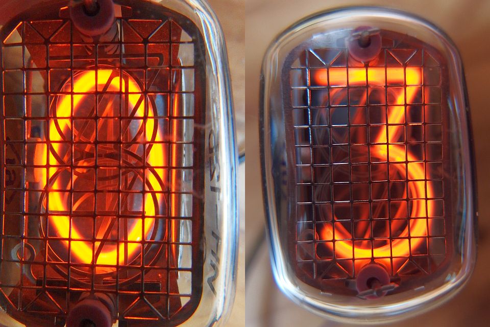
Nixie tube current is chosen as low as possible to extend their lifetime. Some datasheets tell current range of 2 - 3.5 mA and some
2.5 - 3 mA. Minimum is therefore around 2 - 2.5 mA. When the current is to low, it can cause partial glow - only a part of the cathode
is lit. When operating a nixie with a pulsing current, the peak current must exceed the minimum required value.
Resistors R1 - R6 define the nixie current. Resistor R9 is used to fine tune the current and it can be deleted.
Voltage drop of IN-12B nixie is about 130V and the peak voltage of 230V mains is 325V, so at the resistor therefore is 195V peak.
The resistors are chosen so that the peak current slightly exceeded the minimum operating current. R = UR peak. (195V) / Imin. (2-2.5mA).
If the current was not enough to display all digits correctly, you can reduce resistance values.
I chose a peak current of approximately 2.3 mA (average current is about 0.5 mA). It turned out that it is enough to display digits correctly
and also to achieve good readability even in daylight.
Program:
The program for the nixie clock is available for download below in the HEX file (upload directly into the microcontroller) or as source code
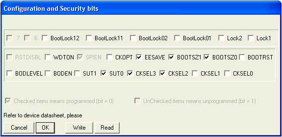
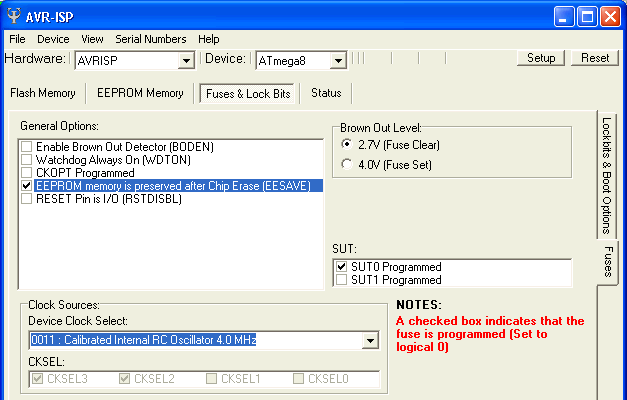
in assembler for possible modifications. The printscreen below shows the microcontroller configuration bits setting in both AVRISP and PonyProg.
The clock is controlled by a low frequency crystal (32 768 Hz), which enables low power consumption when running on battery.
MCU is clocked at 4MHz from the internal RC oscillator. AVR goes into sleep mode Idle when inactive during mains operation.
When battery powered, it uses Power Save mode, enabling very low power consumption. CPU clock is
off in this condition and only asynchronous timer/counter2 is running. The Nixie clock has Operating hours counter. To avoid loss of data (24bit) while disconnected
from both mains and battery, the data are stored in EEPROM and updated 8x per hour. To avoid early EEPROM wear (guaranteed lifetime of each
Byte is 100 000 writes) wear leveling is used. The lowest byte storage is rotated between 96 different bytes
in EEPROM. For higher two bytes it is not needed because the update only occurs on low byte overflow, which is 256x less often.
100 000 writes of a particular byte won't therefore occur before 137 years of continuous operation! EEPROM also holds compensation byte of the crystal.
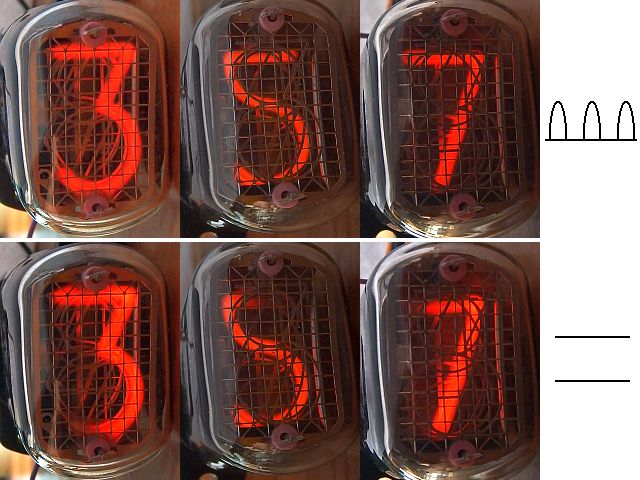
Date and time display cycle repeats every 7 seconds. The number 7 was chosen because it is relatively prime with the numbers 10 and 60,
and thus there is no uneven wear of nixie cathodes of seconds when displaying the time. Time is displayed for 5 seconds and date for only 2 seconds,
because the time is more volatile and therefore more friendly for nixies.
How to set and use the clock:
The clock is controlled by TL1 and TL2 buttons.
• 1. Time/date display
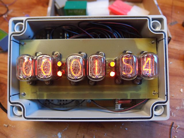
The clock has two basic modes of display. The first one shows only the time in the form "HH:MM:SS" (Hours : Minutes : Seconds).
Second mode alternately displays the time and date with a period of 7 seconds. Time is always displayed for 5 seconds and date for 2 seconds.
Date is displayed in the form "DD.MM.0W" (Day.Month.Weekday). Weekday is displayed using its number (01 = Monday ... 07 = Sunday)
as there's no other way to display weekday on a nixie.
Between these two modes you can switch by pressing TL1. In both modes digits are rotated (slot machine) for 1.25 seconds every 49 seconds.
• 2. Alarm clock
The nixie clock is equipped with an alarm. Button TL2 gradually switching between displaying the time, date-time and four-step alarm settings:
Alarm hours, alarm tens of minutes, alarm minutes and alarm mode. The setting is done using
TL1 button. Alarm modes are: 0 - disabled, 1 - once, 5 - five working weekdays, 7 - every day.
Alarm setting is indicated by alternately flashing dots. Alarm beeping can be stopped by any of the buttons.
• 3. Setting the clock
By long pressing of TL2 you get into the process of setting the time. You set hours, then tens of minutes, minutes, seconds, year,
day, month, day of the week and finally the automatic DST (daylight saving time) shift (111111 = on, 000000 = off).
The setting is done using TL1, switching between the steps using TL2. After four minutes of inactivity, the clock
automatically returns from settings to the time + date display (this protects nixies from static display).
• 4. Automatic DST
If the automatic DST is enabled, the move to summer time takes place on the last Sunday in March. 1:59:59 is followed by 3:00:00.
Move to winter time takes place on the last Sunday in October. 2:59:59 is followed by 2:00:00.
(According to the rules valid in almost all European countries including the Czech Republic and Slovakia since 1996)
• 5. Special functions
Long pressing of TL1 get you into special features. The first one is nixie test in which
all nixies run a chain of numbers from 0 to 9. It can also be used for nixie maintenance (against cathodes poisoning).
Another press of TL2 will take you to another special feature, which is the compensation of the crystal. If the clock is not accurate,
you can adjust it in the range of -75 to +75 ppm with 3ppm (3 millionths) steps. Use TL1 button to set the value.
Negative values are displayed on the left, positive on the right (eg. -12 ppm displays as "12 00 00" and + 75ppm as "00 00 75").
After pressing TL2 you get to the last special feature, which is the operating hours counter.
It displays total nixie operation time (in hours). The following press TL2 longer takes you back to the time display.
Operating hours counter can be reset by a jumper wire connected at DP1 long press of both TL1 and TL2
simultaneously. The dots will flash quickly and the counter is reset to 000000. Resetting is recommended only when you change nixies.
Under normal circumstances it is recommended not to connect the DP1 jumper.
Long term operation experience:
20. 8. 2015 - first 1000h of operation. No failure, no signs of nixie wear.
31. 1. 2016 - 2000 h of operation. No failure, no signs of nixie wear.
The program for free download:
Source code in assembler (ASM)
Compiled HEX file (2 900 Bytes)
How to write the program into the AVR is described here.