Introduction:
This device is intended to remote control appliances and equipment.
It can be used to control toys and models or to add a remote control for devices that do not have one.
It has a total of 10 channels: 2 toggle ones and 8 momentary ones.
The remote control operates on the principle of infrared transmission, with a range of up to 45m.
It combines features of
4 -channel remote control and
Remote Control with 4 commands . It also adds another feature: to use more keys simultaneously (even all 10).
Channels 1-8 are active for the time you press the button, channels 9 and 10 are toggled when you press button.
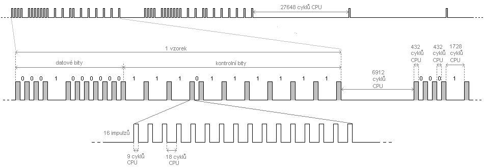
Method of transmission (transmission protocol):
Carrier frequency of this remote control is about 36 to 38 kHz.
The transmission uses PDM (Pulse Distance Modulation). Against PWM (Pulse Width Modulation) it
has the advantage of lower power requirment of transmitter. An encoding method shown in Fig. 2. The long gap (1726 CPU cycles)
between pulses represents log1, short (432 cycles) log0.
The pulse of transmitted signal always has a length of 432 cycles of the CPU and is composed of a 16 impulses of carrier frequency.
In order to transmit separately the status of each of the buttons, the transmitted code has 10 data bits and 10 check bits, which are logical
inverted data bits. The control bits are used to verify the accuracy of the transmission, and making the length of the sample constant.
When you press the button (or pressing another button or release any button while holding the other buttons)
the complete code is always sent twice. Two samples are sent for increased reliability and these two samples are separated by an ultralong space (6912 CPU cycles).
In addition to saving energy and reducing the load of transmitting diode, then the transmitter
transmits just repeating signal consisting of single pulses with a spacing of 27647 cycles (repetition frequency is 35 Hz).
The difference between short and long gaps, between long and extra-long gaps and between the extra-long gap and
a pulse spacing of repetition signal is always quadruple, so the transmission system is resistant to large variations of clock frequencies of
transmitter and receiver. Into this tolerance both deviations of internal RC oscillators (transmitter and receiver) can fit, and it is not necessary to use crystals.
Example code: Button 4 has a binary code 0001000000 and verification code 1110111111. If buttons 3, 4 and 9 are pressed simultaneously,
the code is 0011000010 and the check code is 1100111101.
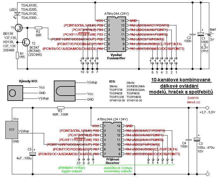
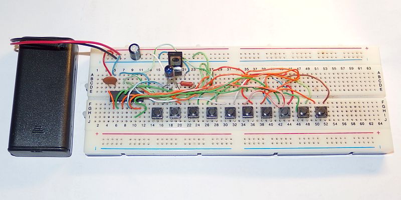
Transmitter (remote controler):
The hearth of remote control transmitter is integrated circuit IO1 - microprocessor Atmel AVR - ATTiny24A or ATTiny24V clocked at a frequency of 1 MHz from internal RC oscillator.
The commands are transmitted by infrared (IR) LED with a wavelength of 940nm. For example TSAL6100, TSAL6200,
TSAL5100 or TSAL5300 in 5 mm standard case can be used (continuous current up to 100mA). When you press the transmitter button, it transmits a corresponding code.
Program ensures that the entire code is always sent 2x, and when the button is kept pressed, repeating signal is being transmitted.
Pulsed current of LED1 is set to about 320 to 400 mA. The current is stabilized by
circuit with T1, T2, R1, R2 and thus do not vary too much with the battery voltage. The current is determined by resistor R1.
The carrier frequency has a duty cycle 33.3 % (9 CPU cycles on, 18 cycles off).
The total duty cycle modulated signal is low, so you can choose a high pulse current and obtain a reasonable range.
Duty of envelope of repeating pulses is 1/65, thus duty cycle of transmitting LED is 1/195.
Transmission frequency is approximately 37 kHz (pulse frequency / 27).
The transmitter is supplied by two 3V AA or AAA cells, or other battery of approx 3V - 4.5V
Minimum catalog supply voltage for IO1 is 1.8V.
Consumption during transmission (repeater) is only about 2-4 mA. When no button is pressed, IO1 enters into power down mode and power
consumption of the entire transmitter is under 1uA (current is much smaller than battery
self-discharge). Capacitor C2 should be placed as close as possible to IO1.
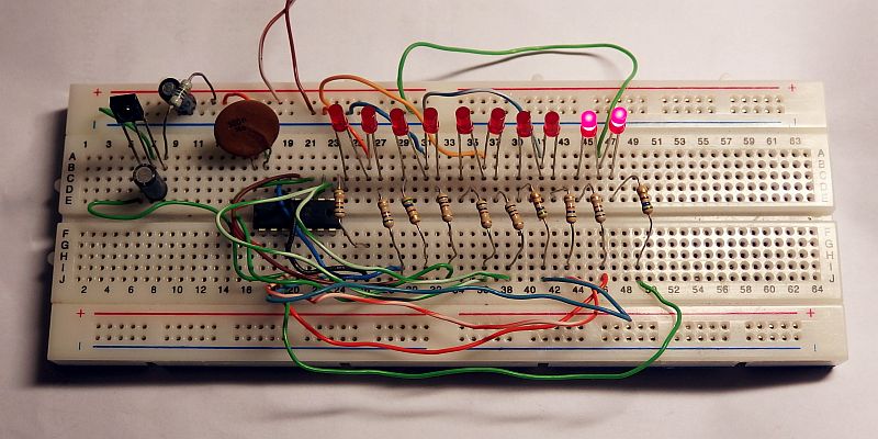
Receiver:
The remote control receiver is controlled by IO2, ATTiny24A, ATTiny24 or ATTiny24V, also clocked at 1 MHz from internal RC oscillator.
As a sensor infrared signal integrated receiver IO3 is used.
You can use receivers for frequency 36-38 kHz (the bandpass filter is wide), e.g. TSOP1736, TSOP4836, TSOP31236, SFH5110-36
OSRB38C9BA, OSRB38C9AA, TSOP4838, SFH5110-38 or TSOP34838. Integrated receiver receives, amplifies and demodulates the infrared signal, it
has a built-in automatic gain control (AGC) and suppression of ambient light, band-pass filter, demodulator and shaping circuit with TTL output.
The receivers are most sensitive to wavelengths of 940 or 950 nm. Transmitting LED must therefore be 940-950 nm, the ones such as 850 nm or 890 nm are not suitable!
The best experience I have with the receiver OSRB38C9BA (much better sensitivity compared with other ones I tested, TSOP1736 and SFH5110-38).
IR receiver output is processed by a microprocessor IO2. It evaluates the received signal, and when it receives a valid code (correct number of bits and the
check bits match the data bits), it evaluates the signal as errorless and responds (it activates output 1-8 or toggles output 9 or 10). After power on,
is the default state of all outputs is log0 (off). Supply voltage 5V can be obtained from a higher voltage using a linear regulator with integrated circuit 7805 or 78L05.
Power consumption of receiver when all outputs are unloaded is determined mostly by consumption of IO3. This is according to its type
about 0.5 - 5 mA. IO2 draws only about 25uA. Supply voltage can range from 2.7 to 5.5V.
Typical pinouts of IO3 are shown in Figure 1, but for your specific type refer
to its datasheet. Capacitor C4 should be placed as close as possible to IO2.
Range:
The range depends mainly on the type and current of transmitting LED1 and sensitivity of IO3. Transmitting LED differs notably its radiant flux (measured in mW)
radiant intensity (measured in mW / sr) and the angle of radiation.
The maximum allowed current Is also important. Caution - radiant flux and radiant intensity in datasheets can be measured at different current!
Maximum range with good directioning (0 degree) is given by radiant intensity. LEDs with the same radiant flux, but the smaller the angle,
have greater radiant intensity. LEDs with a smaller radiation angle
however must be better directioned. At smaller distances, the signal can also reach the receiver by reflections from objects and the direction almost does not matter.
If the transmitter is not well directed, the radiant flux is most important.
I chose IR receiver OSRB38C9BA. The largest range of about 45m I got with the IR transmitter diodes TSAL6100 and TSAL5100.
Diodes TSAL6200 and TSAL5300 provide a range of about 30m, but the direction of the transmitter is less critical.
The program for free download:
Transmitter source code in assembler (ASM)
Receiver source code in assembler (ASM)
Compiled Transmitter HEX file (422 Bytes)
Compiled Receiver HEX file (268 Bytes)