Introduction:
Numitrons, together with nixies ans itrons (VFD),
belong into the group of interesting historical numeric displays.
In nixie tubes, the digit is a glowing cold cathode in neon bulb. In the VFD, it is the phosphor being
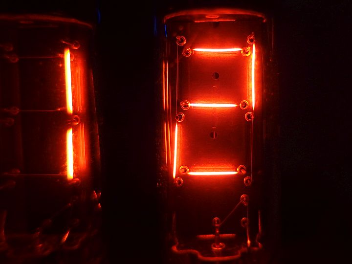
bombarded by electrons from heated cathode in a vacuum chamber. Numitron is different - it works on the principle of conventional light bulbs.
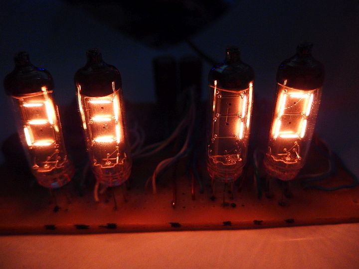
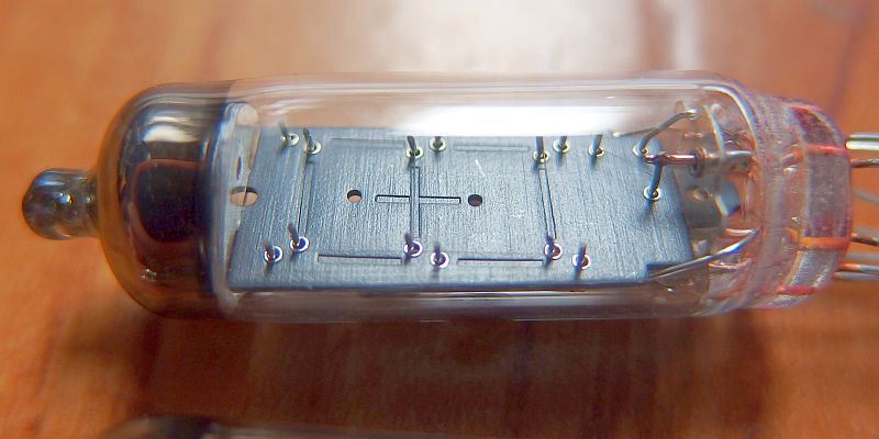
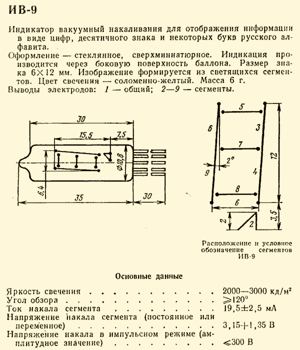
It's actually 7-segment display with segments formed by low-power incandescent tungsten filaments.
It is probably the only historical non-semiconductor display that operates with a very low voltage and can be powered from a common supply with logic.
Numitron device thus only needs one voltage supply, unlike nixie device where you also need anode voltage, or
VFD device, where you need anode and heater voltage. For those interested in the historical displays, who want to work
only with a perfectly safe voltage, numitrons are probably the best choice.
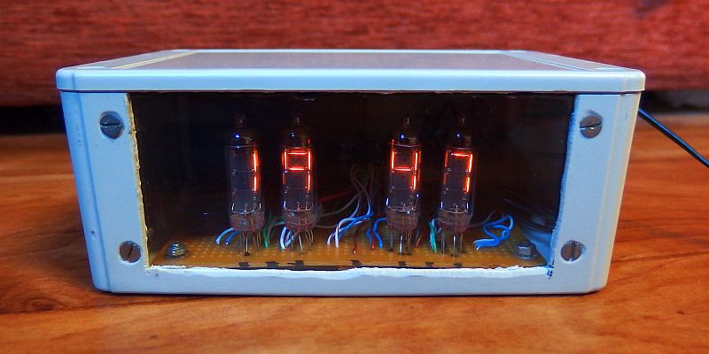
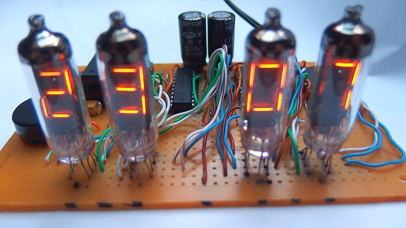
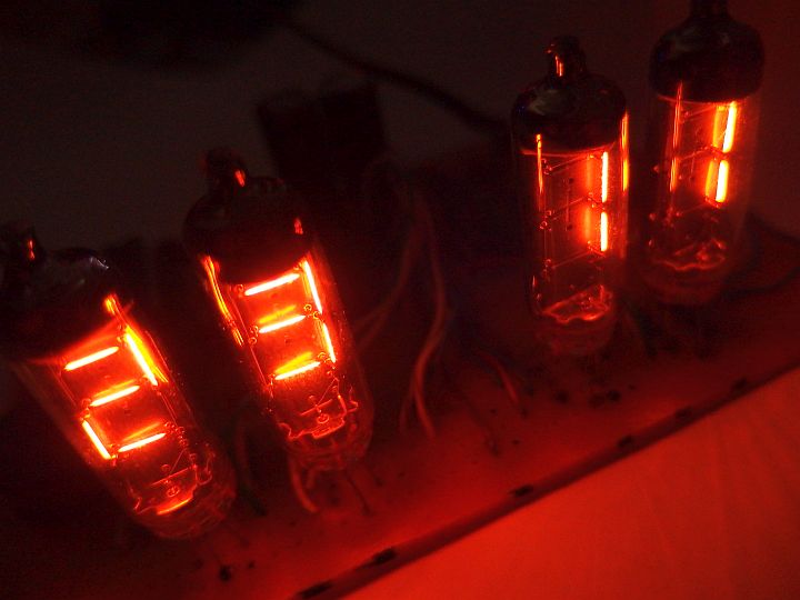
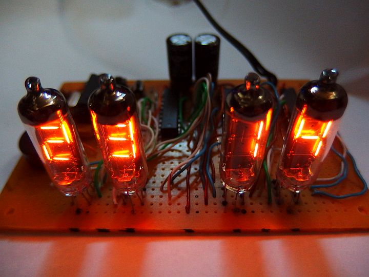
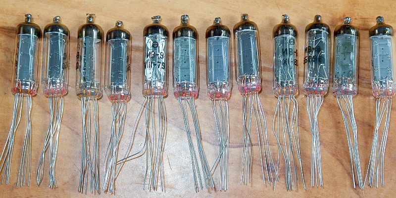
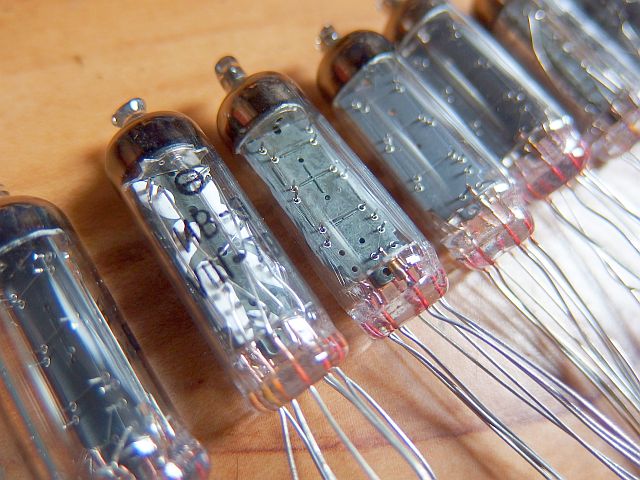
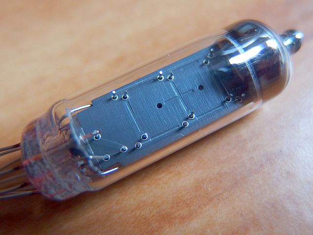
For my clock I chose Soviet numitrons IV-9 (ИВ-9) because they're easy to find and they used to be one of the most common numitrons.
You can also use other types like IV-16 (ИВ-16) that have similar parameters and differ only in the absence of a decimal point.
I finally didn't use the decimal point in IV-9 as a separator of hours and minutes because it has a rather strange shape and is awkwardly placed
below the digit rather than by it's side.
Clock functions:
I didn't want unnecessarily complex functionality. The clock displays just the time (hours and minutes), it has an alarm and operating hours counter.
Seconds are not displayed simply because the frequent changes of data could reduce the life of the filaments. For even longer life of numitrons the digit changes gradually
from one to another during 1.28s using PWM.
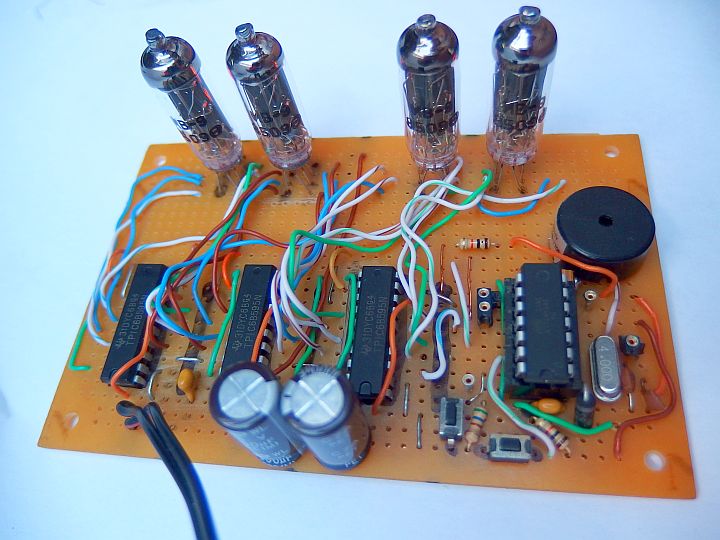
Schematic:
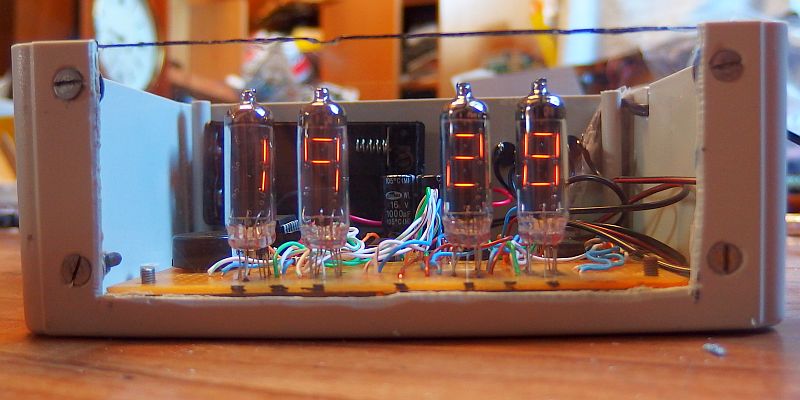
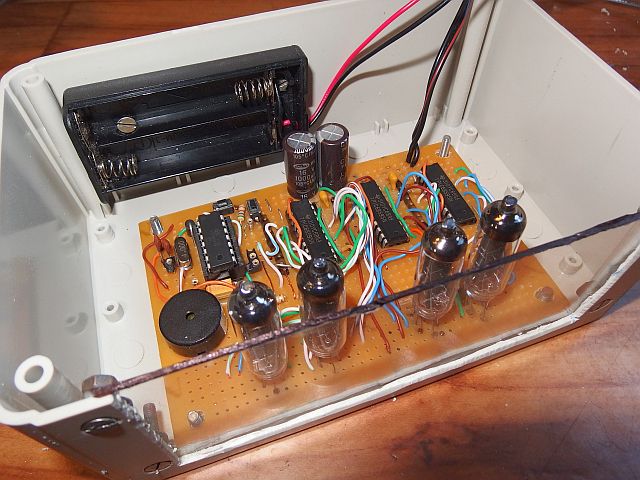
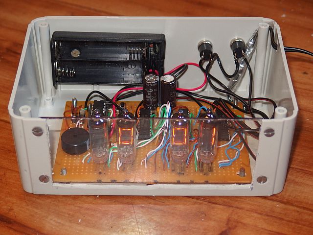
Numitronové clock has a four-digit display composed of four IV-9 numitrons with a character height of 12mm. They are not multiplexed because numitrons are harder
to multiplex than LED displays for example. Multiplex of numitrons requires higher voltage to reach the sufficient RMS voltage,
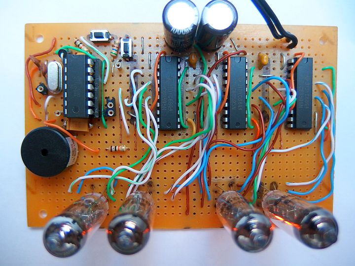
and also requires diodes in series with each segment. That's why I chose operation without multiplex. Numitrons are controlled by power 8-bit SIPO
shift registers TPIC6B595N (or even better TPIC6595N or TPIC6A595NE with a lower output on-state resistance).
Only 3 are needed because the figure dozens of hours is simplified to display only the digits 1 and 2 (f segment
not connected and segments a, d, e, g wired together). The brightness of the segments is controlled by pulse width modulation (PWM) with a frequency of 100Hz.
For IV-9 numitrons drive frequency either below 105 Hz or above 1000 Hz is recommended due to the risk of mechanical resonance.
PWM is also used to ensure a smooth transition from one state to another.
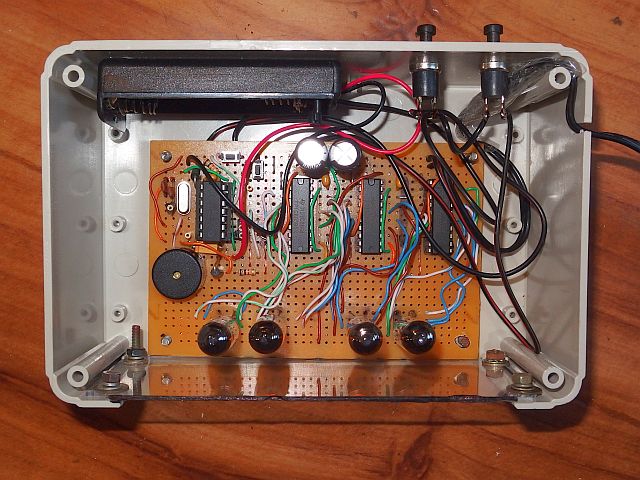
The heart of the clock is the microcontroller IO1 - ATtiny24A or ATtiny24V clocked by 4MHz crystal X1.
Piezo speaker REP1 provides audible alarm signal.
The clock is controlled by two buttons - TL1 and TL2. Pullup resistors are not needed because internal ones are activated in IO1 (20-50k).
The circuit is powered by a 5V supply. The current consumption depends mainly on the numitrons and their brightness setting.
The highest consumption is about 300 mA at maximum brightness and maximum number of lighted segments.
The clock has a backup battery. When operating from battery, the
clocks goes into standby mode - the display is off. Backup batteries can be 3V - 4.5V.
It can be eg. A single coin cell 3V, any two or three cells of 1.5V or three NiMH or NiCd 1.2V cells
or a single Li-ion or Li-pol cell (3.6 - 3.7V). During operation from 3V battery the current is in order of approximately 100uA.
Both power supplies - Mains adapter and battery - are combined using Schottky diodes D1 and D2. D1 prevents reverse current flow from the battery into the mains supply
and protects the numitron clock from the polarity reversal.
D2 prevents unwanted battery charging from adapter power. Schottky diodes should have the smallest possible forward drop and reverse leakage current.
The presence of AC power is sensed through R2 by port PA7.
Program:
The program of the numitron clock is available below to download in the HEX file to be directly written into the microcontroller as well as the source code in assembler.
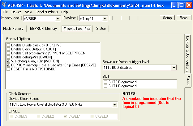
In the picture below you can see the configuration and security bits settings.
The precise time is controlled by a 4MHz crystal.
How to use the clock:
The clock is controlled using buttons TL1 (mode) and TL2 (set).
TL1 button toggles sequentially different modes - time display and alarm settings:
• 1. Time
It this basic mode the real time is displayed in form "HH MM" (Hours Minutes). Button TL2 is used to adjust the brightness of numitrons in 17 steps.
Each time you press the brightness gradually increases. After reaching the maximum the brightness will return the minimum.
• 2. Alarm hours setting
Sets the alarm. In this step, use TL2 button to set hours of alarm. Display format: "HH A"
• 3. Alarm minutes setting
Sets the alarm. In this step, use TL2 button to set minutes of alarm. Display format: "A MM"
• 4. Alarm enable and alarm mode
Use TL2 button to set "A-0" (alarm off), "A-1" (single alarm) or "A-7" (everyday alarm).
Long press of TL1 gets you into operating hours counter display and time setting.
-- 1. Operating hours counter
In this mode the clock displays operating hours counter. Since the 6-digit counter does not fit the display, it is
divided into lower and upper three digits. While holding TL2, the upper three digits are displayed, otherwise the lower three digits are.
For example, clock has had 12,345 hours of operation. When TL2 pressed '012 is displayed and ,345 when it is not pressed.
-- 2. Time setting - hours
Use TL2 to set hours of real time. Minutes are not shown while you set hours.
-- 2. Time setting - minutes
Use TL2 to set minutes of real time. Hours are not shown while you set minutes.
Operating hours counter reset is possible by long pressing of TL1 and TL2 simultaneously when jumper DP1 is connected.
Counter reset is recommended only if you replace the numitrons or if the initial counter value is not zero.
Long term operation experience:
7. 7. 2019 - 33 500 h of operation. No failure, no signs of numitron wear.
The program for free download:
Source code in assembler (ASM)
Compiled HEX file (1 576 Bytes)