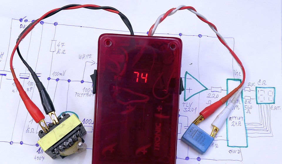
This is an improved version of my Transformer / inductor ring tester .
Again, it can identify a short in the winding, but now including a test in the circuit (in circuitboard without the need for disconnection or desoldering from PCB).
It tests based on the of loss of the inductor or transformer. Even a small number of short-circuited turns (even a single shorted turn)
will cause a significant increase in losses (a significant decrease in the Q factor).
Capacitors can also be tested and their dissipation factor (tan δ) can be estimated using this tester.
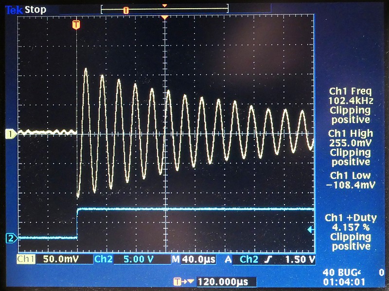
A charged capacitor is connected to the inductor / transformer primary during the test and damped oscillations occur.
The number of oscillations is counted until their amplitude falls below the threshold value.
The previous version used a capacitor charged to 5V and a threshold value of 2.5V, which does not allow in-circuit testing,
because this voltage exceeds the forward voltage drop of the semiconductors.
This version uses only 100mV initial voltage at which semiconductors do not conduct. In most cases, you can therefore test directly in the PCB.
Oscillations are counted until the amplitude falls below the 50mV threshold value (determined by the resistor divider R7, R8).
The number of oscillations is displayed. For damaged windings, this number will be significantly lower.
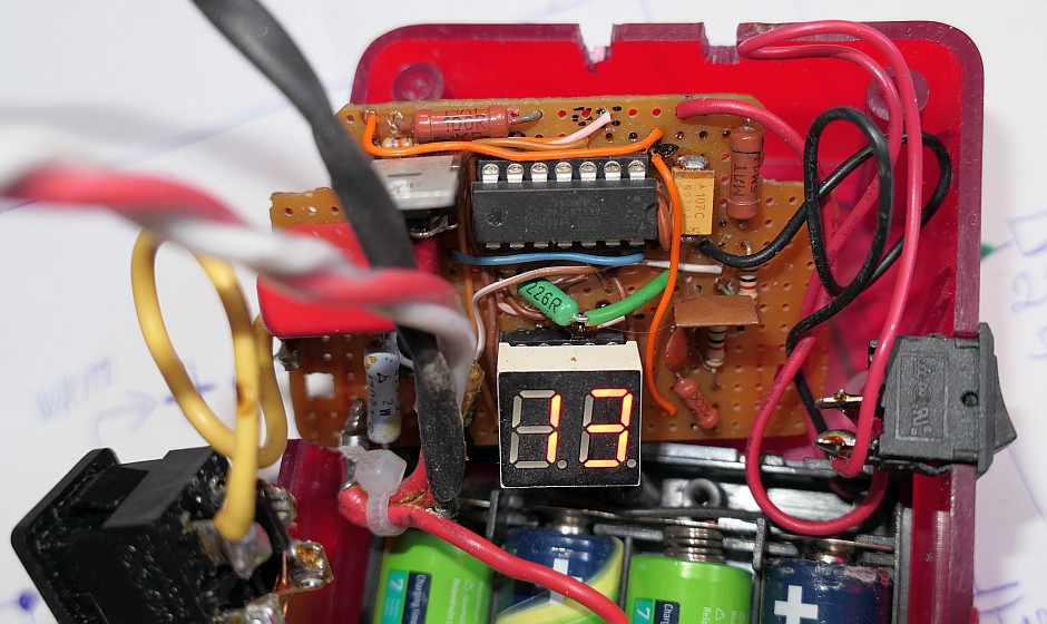
It is displayed using a two-digit common-anode LED display. It is controlled by Atmel AVR ATTiny24A (ATTiny24, ATTiny24V) microcontroller,
the program for download and the configuration bits are below.
The cathodes of the two-digit LED display (a-g) are connected to port PA (except pin PA4).
Anodes are connected to bits 0 and 1 of the PB port. The cathode of the dots (h) is unused, the dot does not need to be displayed.
The use of a high-brightness display allows you to omit the traditional
current amplifying transistors. The display is controlled in multiplex. It is multiplexed in 7 steps, 2 segments in each step, not by digits as usual.
This allows only 2 series resistors to be used instead of seven. The microcontroller is clocked by an internal RC oscillator operating at 8MHz frequency.
The multiplex frequency is about 100 Hz. Resistors R10 and R11 determine the current of the display and thus its brightness.
Consumption at 4.8 V supply is approx. 1 - 3 mA if nothing is connected to the test terminals, and approx. 3 - 12 mA during testing
(depending on the number of illuminated display segments).
The circuit can be powered, for example, from a 5V switching power supply, a power bank, a linear power supply with a 7805 circuit or
4 rechargeable 1.2 V NiMH or NiCd cells. I used 4 NiMH AA cells.
Insert a suitable fuse before the power supply! Place the C2 ceramic capacitor as close as possible to pins 1 and 14 of the microcontroller.
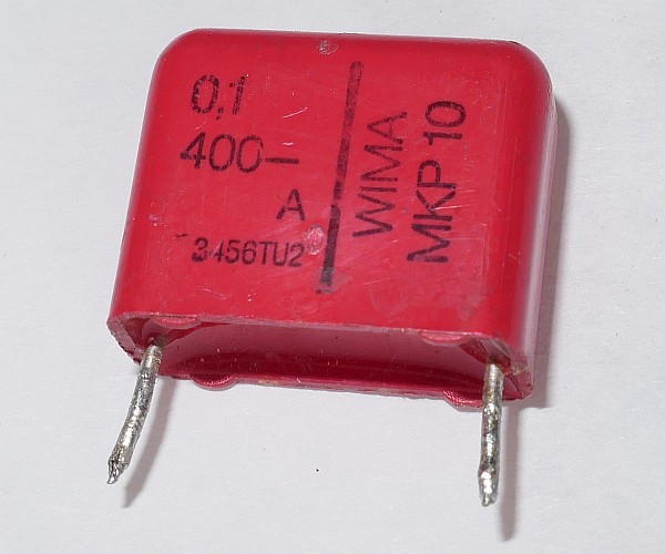
Capacitor C3 is quite critical and must have a very low dissipation factor (tan δ), I recommend using a high-quality polypropylene film capacitor.
Please note that the circuit will not work with a ceramic capacitor and only very poorly with a polyester one.
Transistor T1 is an N-channel MOSFET with a sensitive gate (logic MOSFET).
With the supply voltage (minus a certain voltage drop in the output of the microcontroller) on its gate,
it must already have a very low on state resistance (ones of milliohms). Therefore, it is also better to use a power supply of approx. 4.8 - 5V, not less.
Switch S1 is used to turn the tester on and off. When the transistor is off (about 100 ms), the capacitor
C3 (or external capacitor Cx) is charged from the R1 and R2 resistive divider to about 100mV through the tested inductor or transformer.
When the transistor turns on (about 150 ms), there are damped oscillations that are
monitored by the comparator TLV3201. If the voltage is above approx. 50mV, the output of the comparator is high.
During every damped oscillation that reaches above 50mV, there's therefore
a pulse going to PA4 input of the microcontroller and it is counted. The measurement is repeated every 250ms, so the data on the display is refreshed at about 4 Hz.
The inductor or transformer can be tested using an internal capacitor C3 connected using switch S2, or using an external capacitor.
The contact resistance of switch S2 is quite critical, it should be as low as possible.
It would definitely not be bad to use a MOSFET instead (between C3 and T1) and control its gate using a switch.
The tester also allows you to test capacitors. Connect the capacitor to the terminals for the external capacitor. Connect an inductor to the inductor test terminals
with a suitable inductance and the highest possible Q factor. The more oscillations, the lower the dissipation factor of the capacitor.
The frequency of damped oscillations is, of course, influenced by both the capacitance of the capacitor and the inductance of the inductor or transformer.
Resistor R4 and diodes D1 - D3 are mainly used to protect the tester when accidentally connected to a charged capacitor or a circuit with a charged capacitor in it.
If no inductance is connected, a dash will appear on the display. This condition is detected thanks to the pullup resistor R5 which
will permanently bring a positive voltage higher than the threshold value of 50mV (limited by D3) to the the non-inverting input of the comparator.
The terminals of the external capacitor can be omitted and only the internal C3 can be used, or vice versa,
you can work only with the external capacitor. This eliminates the problematic switch S2.
The Brown Out Detector (BOD) level of the microcontroller can be set to 2.7V or to 4.3V. Setting it to 4.3V may prevent discharging 4 NiMH cells
too low or operating the tester below the minimum voltage necessasy for its proper operation.
The AVR program for download:
source code in Assembly (ASM)
compiled HEX file (374 Bytes)
Low fuse = E2, High fuse = DD (BOD level 2.7V) / DC (BOD level 4.3V), Extended fuse = FF, Lock fuse = FF