Intro:
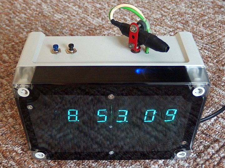
I decided to build a clock with a vacuum fluorescent display (VFD), also called Itron. To add the clock an extra feature,
I equipped it with a DCF-77 receiver. The clock is automatically set to accurate time. It also has
date, automatic summer and winter time, alarm and adjustable brightness. Because I was very satisfied with the DCF-77 clock,
I also decided to build a LED display version of DCF-77 clock.
Circuit:
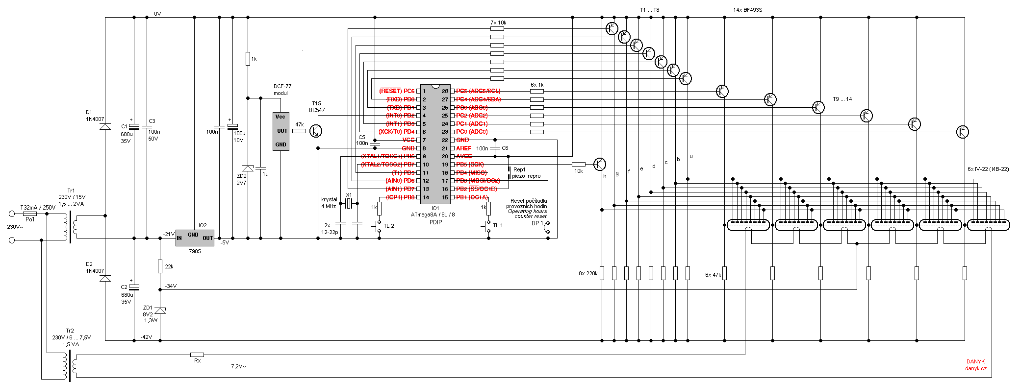
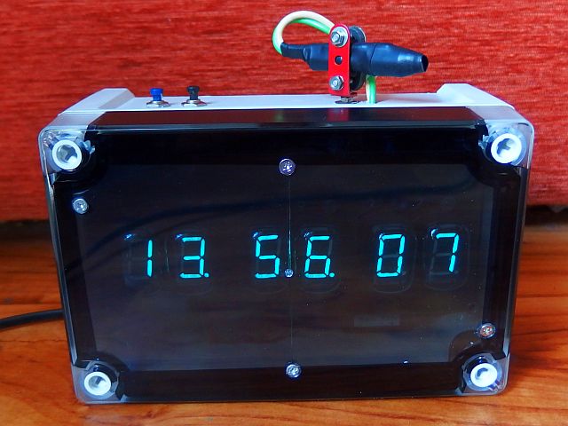
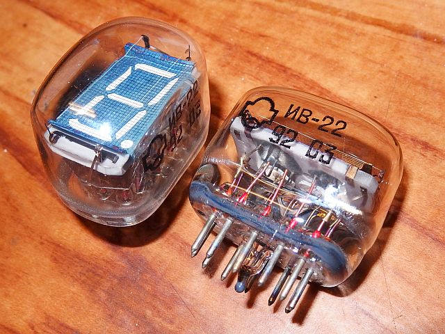
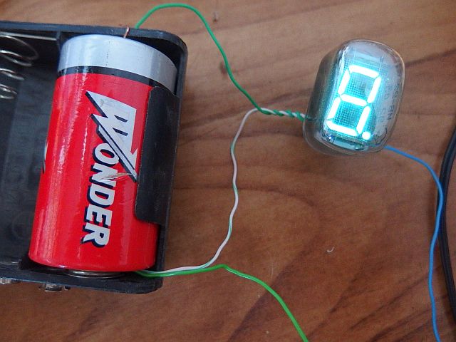
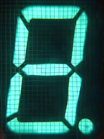
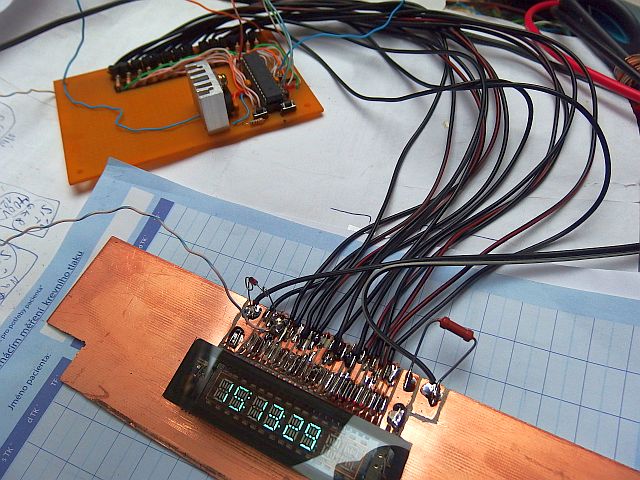
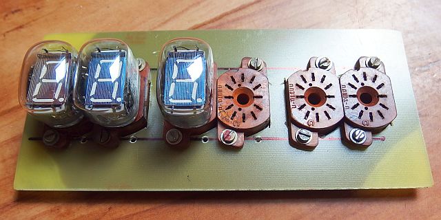
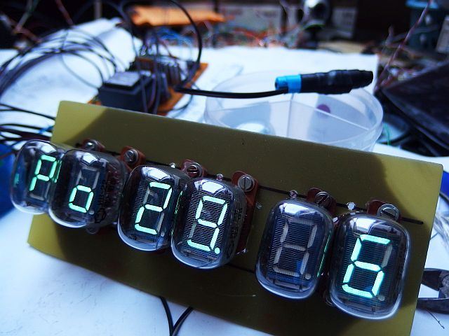
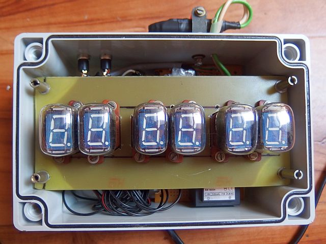
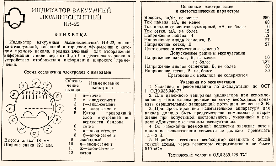
The clock has a six-digit display made of six single-digit Soviet VFD displays IV-22 (ИВ-22).
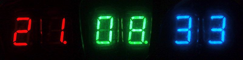
Almost any VFD can be used, e.g. IV-3, IV-6, IV-11, IV-12, or even modern flat monolithic VFD, as long as the heating voltage is correctly chosen.
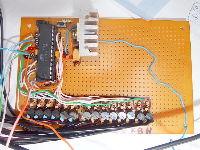
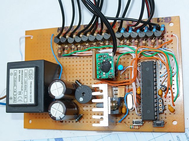
As a control circuit I chose the Atmel AVR ATmega8A (ATmega8, ATmega8L). It provides all functions required for clock operation.
It is clocked from 4MHz crystal.
Power is provided by two mains transformers: Tr1 and Tr2. Tr1 (15V) provides anode voltage for VFD and voltage for the microcontroller.
Anode voltage of about 42V is obtained by doubler. 5V voltage for microcontroller is generated from 21V using a circuit 7905,
which is similar to the famous 7805, but working with a common positive pole.
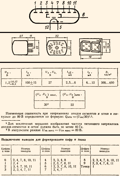
Tr2 provides alternate heater voltage for VFD display. IV-22 heater is rated 1.2V and 100mA. In case of series connection you need
7.2V and 100 mA. Series connection has been selected, since ready made transformers usually don't offer low output voltage, such as 1.2V.
You can use any transformer with secondary rated at least 100mA and 7.2V or a bit more, using Rx to reduce the voltage to 7.2V.
I originally intended to 7.5V transformer. But because small transformers tend have much higher secondary voltage at less than full load,
it turned out that even when using a 6V / 1.5VA transformer, the output voltage
at 100 mA load is still higher than 7.2V and still needs a series resistor. The center of the heating circuit is used as the cathode. It is connected to
the Zener diode ZD1, which determines the cutoff voltage of VFD. To make the segment totally dark, anode and grid need a negative voltage against cathode.
The negative voltage is needed sufficiently high because the cathodes are directly heated and thus the heating voltage is superimposed.
Voltage of anodes and grids is switched via high-voltage PNP transistors T1 ... T14 rated to at least 80V. They are connected with
a common emitter. The bases are controlled from the microcontroller IO1. Inactive anodes and grids are pulled down to a
negative voltage via resistors. The display is controlled in multiplex with frequency of about 100Hz. A positive voltage is applied always to
the grid of one digit and at the same time to the desired anodes (segments). Segments of VFD light up only when a positive voltage is applied
to the anode and grid at the same time. This enables simple multiplexing of VFD displays.
PC0 output activates the most right digit, PC1 activates the 2nd digit from the right ... PC5 activates the most left digit.
Piezo speaker Rep1 provides audible alarm signal. It can be replaced with an induction speaker with a capacitor in series (cca 1uF).
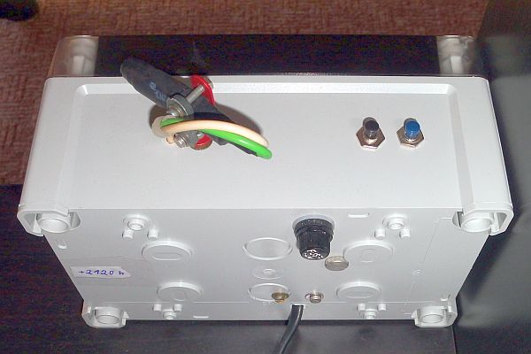
The clock is controlled by the buttons TL1 and TL2.
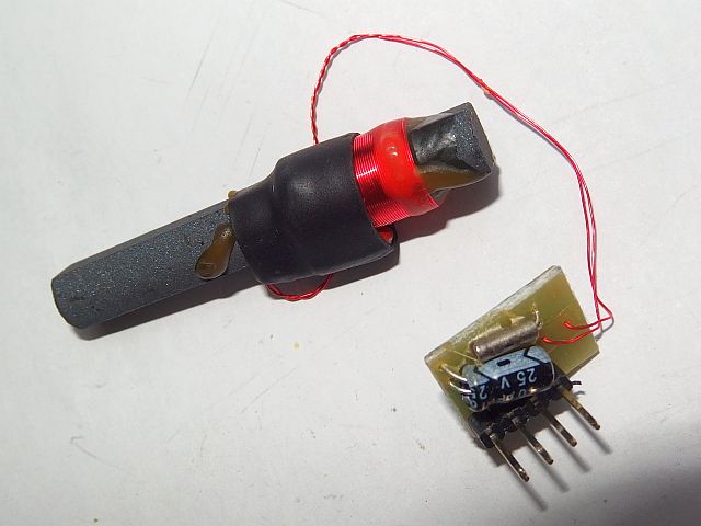
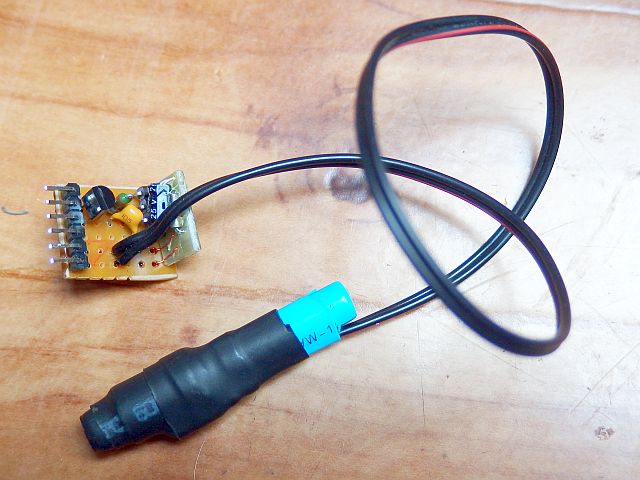
DCF-77 module has a voltage range from 1.2 to 3.3 V, the consumption is less than 90uA. The power for it can be obtained by a simple
regulator with Zener diode ZD2 (which can also be replaced by a white or blue LED).
The regulator also helps to suppres the digital noise coming from
microcontroller. Since the receiver is powered by a lower voltage than the microcontroller, logic levels are adjusted by T2.
The output signal of module is positive (the pulses of 100ms or 200ms are log.1) and transistor T2 inverts the signal,
so the program expects negative signal (pulses are log.0). The signal enters the pin PD2 (INT0).
DCF-77 reception:
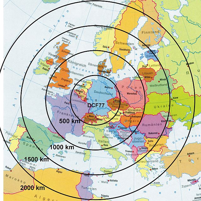
This clock receives signal from DCF-77 transmitter located in Mainflingen near Frankfurt, Germany. Its range is up to 2000 km and covers
most of Europe. Time information is transmitted on longwave frequency of 77.5 kHz, amplitude modulated, with 50 kW power. Complete time data is broadcasted
every minute. At the beginning of every second it transmits a mark by reducing the amplitude to 15%. The mark is 100 or 200ms long. The 100 ms mark denotes binary 0,
the 200ms mark denotes binary 1. Therefore, 1 bit per second is transmitted. For reception it is advisable to use a ready made module. It has demodulated
signal on its output - a positive pulses with a length of 100ms or 200ms each second. Exception is the 59th second of every minute with no
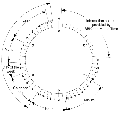
pulse transmitted. This indicates that the next pulse will mark the beginning of a new minute. The meaning of the bits are shown below.
Zero bit (beginning of a new minute) is always binary 0 (100ms pulse) and together with the previous missing pulse it implies the real time seconds just turned "00".
Bits 1-14 contain weather forecasts or civilian warning. Weather is utilized in various home weather station.
Encoding method for weather forecast does not seem to be officially published.
Probably for the purpose of monopoly on sales of weather stations and thus their increased earnings.
There are only some results of reverse engineering and attempts to decipher the cipher by various enthusiasts. Whether their disclosure is legal I have no idea.
However, for the purpose of this clock those bits are not important. Bits 15-19 contain information about abnormal transmitter operation,
daylight saving time (upcoming summer or winter time switch), and information about upcoming leap seconds. Those are also not needed.
For our purposes, only bits 20 to 59 and a zero bit are important.
They contain information about the time (minutes, hours, day, month, day of the week, year) and parity check bits.
So we have to receive just bits from bit 20 to bit zero. The bit 59 is missing, so we only need 40-bit long information.
Bits 1-19 are ignored.
To successfully synchronize the clock, thus, we need flawless signal reception at least from 20th second to zero seconds (start of a new minute).
After the first activation of the clock thus the sync takes from 40 to 100 seconds according to the moment of powering it on.
Received bits are gradually being rolled into the five 8-bit regiters, total of 40 bits. Excess bits overflow.
After the last bit was received (the bit that comes after a 2-second gap), the shift registers contain data from 20th second to zero (bit 59 is not included).
Then the data are being decoded. They are checked for correctness by all available means.
Three parity bits are checked (for minutes, hours and date). Furthermore, it is checked whether the bit zero was a "0" and the 20th bit was "1".
It is also checked whether the numbers are within the permissible range (ie minutes 00-59, hours 00-23, day 1-31, month 1-12, day of week 1-7)
and whether any BCD code does not contain prohibited values (ie value of more than 9).
Finally the clock checks, if the time sample is consistent with previous one.
If everything is correct, the data are loaded into the clock.
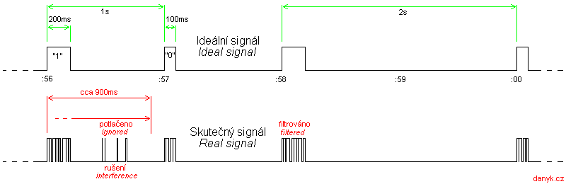
It should be noted that the output signal from the receiver module certainly does not have to be perfect.
It turned out that the pulses at the output are not clean single pulses 100 or 200 ms long, but they are scattered to a sequence of short pulses, see
the image below. The program must filter out short gaps during the pulse. My program
evaluates falling edge only if the signal remains low longer than 25ms. We also need to filter pulses in random places
between the actual pulses from the transmitter. Short random pulses are suppressed already on the basis of their insufficient length.
Since the transmitter pulses arrive every 1s, it is also possible to distinguish longer random impulses from the transmitters impulses because they come
too soon. The program thus ignores pulses that occur within 900ms from the beginning of the previous evaluated pulse.
Thanks to this, the clock is correctly synchronized even if the signal is of lower quality.
The pulses are encoded using decrease of transmitter power. Interference from other sources will be added to the power of the transmitter and demodulator
receives them as gaps within the pulse. Short time signal fading causes unwanted output pulses, since
they behave similarly as a decrease in transmiter power. Without a software fixing, the signal is almost unusable.
The receiving antenna is ferrite. Ferrite rod is to be placed horizontally sideways to the transmitter.
Program:
The program of the DCF-77 VFD clock is available for download below in the HEX file (to be uploaded directly into the microcontroller) or as source code
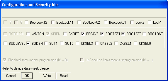
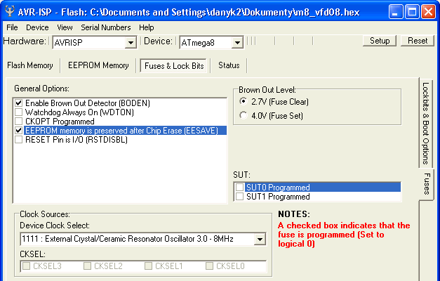
in assembler for possible modifications. The printscreen below shows the microcontroller configuration bits setting in both AVRISP and PonyProg.
The MCU is clocked by a 4MHz crystal. The VFD clock has Operating hours counter. To avoid loss of data (24bit) while disconnected
from both mains and battery, the data are stored in EEPROM and updated 8x per hour. To avoid early EEPROM wear (guaranteed lifetime of each
Byte is 100 000 writes) wear leveling is used. The lowest byte storage is rotated between 96 different bytes
in EEPROM. For higher two bytes it is not needed because the update only occurs on low byte overflow, which is 256x less often.
100 000 writes of a particular byte won't therefore occur before 137 years of continuous operation! EEPROM also holds
brightness setting, night dimmimg setting, automatic summer / winter time and defauld display mode, so that it is
preserved even with no power.
How to use and this clock:
The clock is controlled by TL1 and TL2 buttons.
• 1. Time / date display
The clock has two basic modes of display. The first one shows only the time in the form "HH.MM.SS" (Hours : Minutes : Seconds).
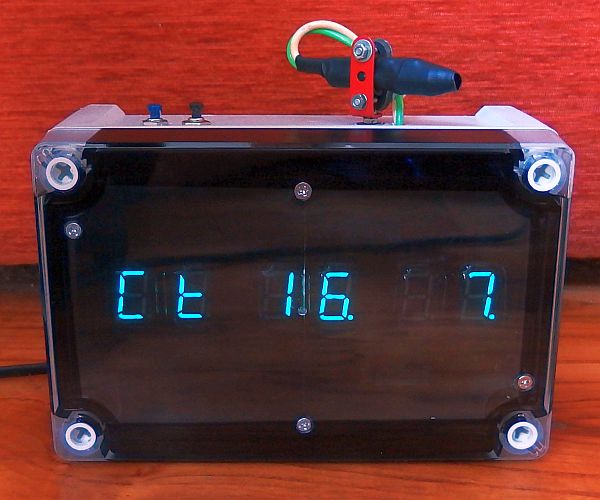
Second mode alternately displays the time and date with a period of 7 seconds. Time is always displayed for 5 seconds and date for 2 seconds.
Date is displayed in the form "WW DD.MM" (Weekday Day.Month).
Use TL2 to switch between time display, time+date display and alarm setting.
Use TL1 to set display brightness in 6 levels (1/32 - 1/16 - 1/8 - 1/4 - 1/2 - max).
If there was a successful synchronization with DCF in the last 10 minutes, the decimal points in hours and minutes display are flashing
with a frequency of 1Hz. Otherwise they are lit continuously. At the moment of successful synchronization they blink rapidly (4 Hz).
The decimal point in seconds display flashes according to raw
pulses from DCF receiver and it indicates its correct function (every second it blinks for 0.1 - 0.2s).
• 2. Alarm
This VFD clock is equipped with an alarm. Button TL2 gradually switching between displaying the time, date-time and four-step alarm settings:
Alarm hours, alarm tens of minutes, alarm minutes and alarm mode. The setting is done using
TL1 button. Alarm modes are: 0 - disabled, 1 - once, 5 - five working weekdays, 7 - every day.
Displayed as: "hh.mm.Ax" (hh = hours, mm = minutes, x = alarm mode).
Alarm sound can be stopped using any button.
• 3. Manual setting, special functions
The clock is automatically set using DCF-77 radio signal, but if necessary it can be set manually.
Long pressing TL2 you get to time settings and special functions and settings.
Then you go through the setting proces using TL2. Use the TL1 to change the setting.
First, total time of operation (in hours) is displayed. The following press TL2 displays the time elapsed since the last successful sync
with DCF. Another press of TL2 displays various raw data from DCF receiver - counter of received bits, bit value and receiver state.
The last two digits are the seconds of real time.
Another press of TL2 get you into the process manual time setting.
You set hours, tens of minutes, minutes, seconds, year, day of the week,
day and month.
In the next step you can select the language for the day of the week (dAY CE - Czech, dAY En - English).
Then you set night dimming (n.di).
A value of 0 means off. Values 1 and 2 indicate that at night (9:00 p.m. to 5:00 a.m.)
the display brightness is reduced by 1 or 2 levels.
Next, you set the automatic switch to daylight saving time (dSt). The value 0 means off, 1 means on.
In next step you can enable / disable synchronization with DCF-77 signal (dCF). The value 0 means off, 1 means on.
Another press of TL2 takes you into alarm settings (already described above), then to the basic display.
• 4. Automatic summer / winter time
If the automatic DST is enabled, the switch to summer time takes place on the last Sunday in March. 1:59:59 is followed by 3:00:00.
Switch to winter time takes place on the last Sunday in October. 2:59:59 is followed by 2:00:00.
(According to the rules valid in nearly all European countries including the Czech Republic and Slovakia since 1996)
• 5. Operating hours counter reset
Operating hours counter can be reset using jumper wire connected at DP1 and then long press of both TL1 and TL2
simultaneously. Then the counter is reset to 000000. Resetting is recommended only in case of VFD display replacement.
Under normal circumstances it is recommended not to connect the DP1 jumper.
Long term operation experiences:
13. 2. 2019 - 29 700 h of operation. No failure, no signs of wear.
The program for download:
Source code in assembler (ASM)
Compiled HEX file (5 188 Bytes)
How to write the program into the AVR is described here.