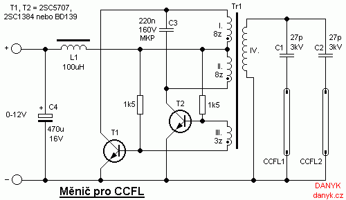
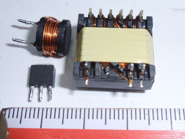
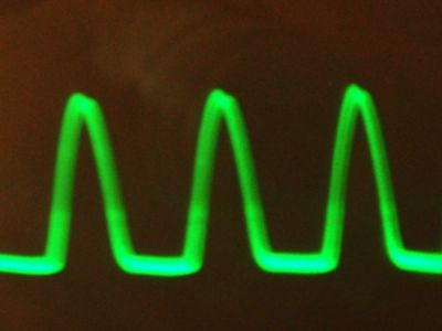
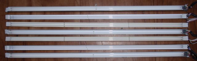
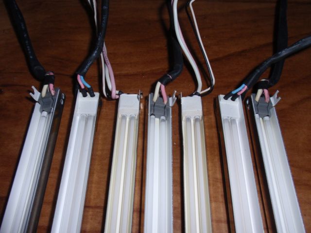
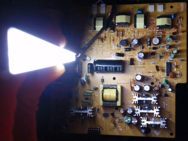
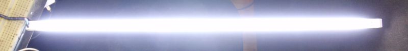
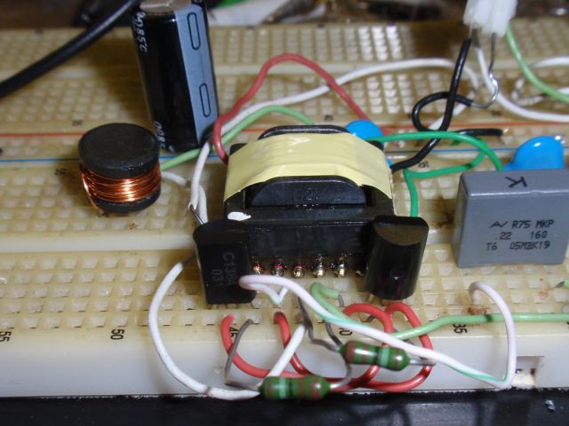
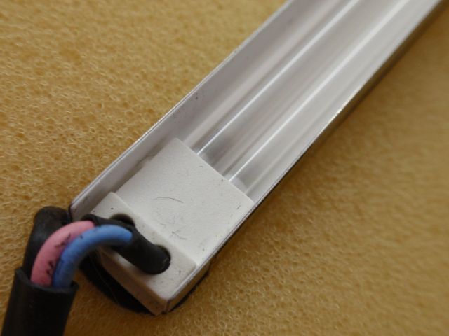
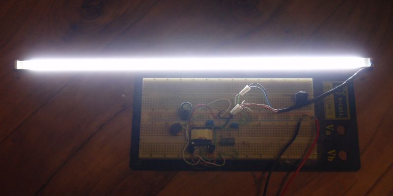
CCFL inverter is a circuit that is used to power the CCFL lamps (CCFL = Cold Cathode Fluorescent Lamp). These circuits usually use simple converters operating at high frequency and using high voltage miniature transformer. Output current is limited capacitively using a high voltage (few kV) capacitor with a small capacitance (tens of pF). Cold cathode fluorescent lamp (CCFL) has only two outlets, because it has no preheating. It is used most often for backlighting LCD panels in monitors and LCD TV sets, and also PC tuning, car tuning and decorative effects. It is also possible to use them for illumination. In addition, there are white as well as color and UV (black light) CCFL available. Capacitive current limiting is possible because the output voltage is sinusoidal. The inverter operates in resonant mode. It is an current fed inverter. This is ensured by L1 choke. Current of the fluorescent tubes (and thus power) can be adjusted by changing C1 and C2. Operating frequency is about 50kHz. It can be adjusted by C3. By changing the frequency the power is also changed. The brightness of fluorescent lamps can be controlled by changing the supply voltage in range from 5V to 12V. Control is possible in the range from about 5 or 10% to 100% brightness. With less voltage than 5V, it may happen that only a part of the lamps will be lit. One end of the lamp starts to glow at cca 1.5 V and the entire CCFL lamp is lit from 5V. When connecting CCFLs to Tr1 transformer observe the cold and live end (the cold end of the transformers and fluorescent tubes have thinner insulation than those live). The circuit I tested successfully with transistors 2SC5707, 2SC1384 and BD139. Tr1 can be obtained from the LCD monitor, or other device with CCFL. Winding your own would be difficult due the large number of turns of a thin wire at secondary. It is possible to rewind PRIMARY of transformers that originally had only one primary (those intended for converters with MOSFET and control integrated circuit). You can use another number of lamps - it depends on the power of the transformer. I tested the drive on tubes 2x350mm of 17'' monitors. I identified them as type with parameters: 1200V start voltage, 850V operating voltage, maximum current of 5 mA, max power 4.25 W, The rise time of minutes, the drive frequency of 20 - 100kHz. Inverter efficiency is about 80-90%, so the input power of tubes can be estimated as 0.85 x power input of the inverter, so Ptubes = 0.85 x U in x Iin. With a 12V power supply, therefore, these two tubes should draw 833 mA. If power does not match, it can be adjusted by varying capacities C1 and C2 (smaller capacitance = less power). It can also be fine adjusted by changing the frequency by changing the value of C3.