Introduction:
Simple digital frequency meter has many applications. It may be an experiment for beginners, laboratory equipment
or a meter built into some device. Ideal wherever there is a need to measure and digitally display the frequency.
Circuit description:
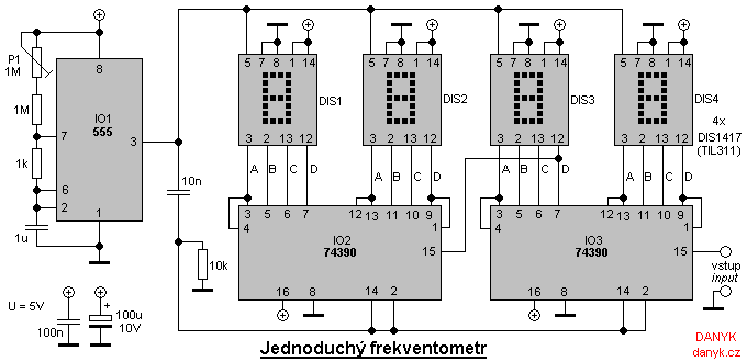
The frequency meter is built only from common components (logic), without a microprocessor (microcontroller) that have to be programmed.
The basis is 74390 double decimal counter (74HC390 - CMOS, 74LS390 - bipolar). Oscillator with IO1 (555) determines the time of counting.
With the component values listed in the schematic diagram below, the counting time is 1s. Frequency meter therefore measures with a resolution of 1Hz.
The displays are DIS1417 or TIL311. They have already built LATCH circuits and decoders from BCD to 7 segments.
This eliminates the need to use external ones. If you would like to use the standard 7-segment display, it would be necessary to use
external LATCH (eg 4-bit 7475 / 74HC75 / 74LS75 8-bit or 74373) and decoders (eg 7447 or 4543).
Circuit 555 (IO1) produces rectangular signal at its output (pin 3) staying in log 1 for 1 second, followed by a short pulse of log 0.
During log 1 the counters counts, during the negative pulse are the data on displays refreshed and counters are reset.
This is done in two steps: At the falling edge the LATCH feature is turned off and the values in the counters are transmitter to the displays,
and the rising edge of the counter then resets the counters to be prepared for next counting cycle.
Frequency meter on the schematic measures in the range 0 to 9999 Hz with a resolution of 1 Hz. However, any number of digits can be chosen
and also you can choose different measurement periods. If we choose as 0.1 s, it will measure up to 99.99 kHz with a resolution of 10 Hz.
If we choose 0.01 s, frequency meter will measure the frequency up to 999.9 kHz with a resolution of 100Hz.
When we choose a shorter counting interval it is appropriate to extend the log 0 to reduce the refresh rate.
If the display refreshs 10x or even 100x per second, the value can unreadable during measurement of variating frequency.
The advantage of controlling the measuring time with RC oscillator with 555 circuit is its simplicity. The disadvantage
is a slightly worse accuracy. For more accurate measurements
the crystal oscillator can be used.
Adjustment:
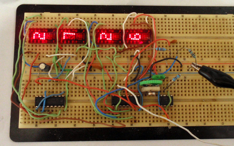
The adjustment of the frequency meter is simple. Hook it to a power supply (about 5V)
and connect known input frequency. Then set the trimmer P1 to display the correct value.