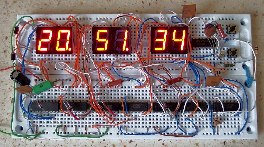
This simple clock displays time in HH.MM.SS format in 24-hour mode.
It's made from common and easily available CMOS integrated circuits:
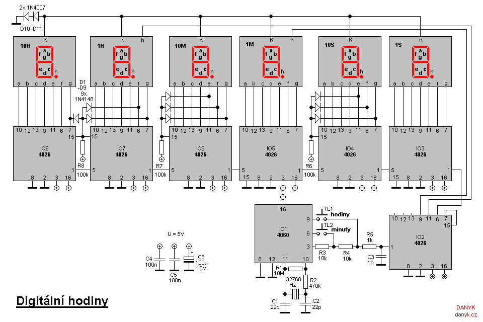
Crystal oscillator with a prescaler 4060 and seven decimal counters 4026.
4060 circuit (IO1) divides crystal frequency 32 768 Hz using a 14-stage binary prescaler down to 2 Hz frequency.
The decade counters 4026 are interesting because they have direct outputs for the 7-segment display.
Unlike conventional BCD counters, they don't need a decoder from BCD to 7 segments.
Active level is high (log 1), so we use displays with common cathode.
They also have Carry Out output (pin 5), which
increments the next counter during overflow. 2 Hz frequency must be first divided by two in order to get 1Hz for seconds.
This is done by IO2. For simplicity it is also 4026, despite it doesn't have any display connected.
The 2Hz signal enters its CLK input (pin 1) through R3, R4, R5. Counting cycle 10 is shortened to
2 using reset input (pin 15). Since it doesn't have any BCD outputs, we connect the reset input to segment g output. Segment g is not active
for the digits 0 and 1, but it is active (high) for the digit 2. Therefore, when the counter reaches state 2, it almost immediately resets and gets into state 0.
Thus, only the digits 0 and 1 alternate with a frequency of 1 Hz. 1Hz signal is available at 4 different outputs - the outputs of segments a, d, e, f.
These can be used to control the seconds and also to power the flashing dots. For load balancing, we will use any two of them to power the dots and third one
to clock the ones of seconds - pin 1 of IO3 circuit. Note that Carry Out pin (5) of IO2 can't be used as 1Hz output! It only works for division
by 6 to 10, since it is high for states 0 to 4 and low for states 5 to 9. When dividing by two, Carry Out pin is always high and never changes its state.
Counters at ones of seconds and ones of minutes count from 0 to 9 (base-10), and require no modifications.
Circuits at tens of seconds and tens of minutes must count from 0 to 5 (base-6). It is therefore necessary to shorten its counting cycle.
At 6 it must reset - go immediately to state 0. As there are no BCD outputs, we must distinguish the state 6 using
outputs for segments. We will use segments e, f, g. In state 6, those three segments are all high for the first time.
Reset input (pin 15) is connected to these 3 segments using DRL (diode-resistor logic) forming a 3-input AND gate.
Before the state 6, the reset input is held low via at least one of the diodes. In the state 6, reset input is pulled high
by a resistor (R6 or R7) and the counter goes almost immediately into state 0.
Ones and tens of hours must go to 00 after 23. Both counters are reset at state 24
(units of hour at 4 and tens of hours at 2). Again we use a simple diode-resistor logic
connected to segment g of tens of hours and segment f, g of ones of hours. These three segments are all simultaneously high
for the first time at 24 and in this state both counters will reset to 00 (both reset pins are pulled high by R8).
Output current of 4026 circuits is not very high (about 1-3 mA) and thus the display doesn't need series resistors.
(Otherwise we would have to use 44 of them - for 6x 7 segments and 2 dots).
Voltage at the outputs drops to a forward voltage drop of LEDs. But the outputs need to have sufficient voltage to generate high level (>3.5V) at reset inputs.
Since the forward voltage drop across the LED is lower, we increase it by using diodes D10 and D11 in series.
If the counters still don't reset correctly (hours after 23 and minutes or
seconds after 59 to 00), try to add another diode in series with D10 and D11.
Adding more diodes can also reduce brightness of the display and power consumption of the clock if needed.
Another possible cause of imporoper resetting may be too high value of R6, R7, R8 (too slow voltage rise at reset inputs). In such
case, use lower values for resistors R6, R7 or R8.
This clock is set using the TL1 and TL2 buttons. First, set hours using TL1 and then minutes using TL2.
During setting, the buttons simply bring higher frequencies to the counter chain. Resistors R3, R4 prevent conflict of two outputs when buttons are pressed.
Resistor R5 and capacitor C3 remove button bouncing.
Running speed of the clock can be fine tuned by changing the values of C1, C2, or you can use capacitive trimmers.
The clock is powered by a 5V supply, current consumption is about 120 mA at most. Parallel to the power supply connect an
electrolytic capacitor at least 100uF and at least one blocking ceramic capacitor 100nF (preferably more of them in different locations,
so that the path between these capacitors and integrated circuits is not too long).