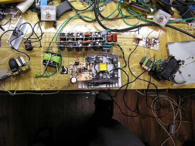
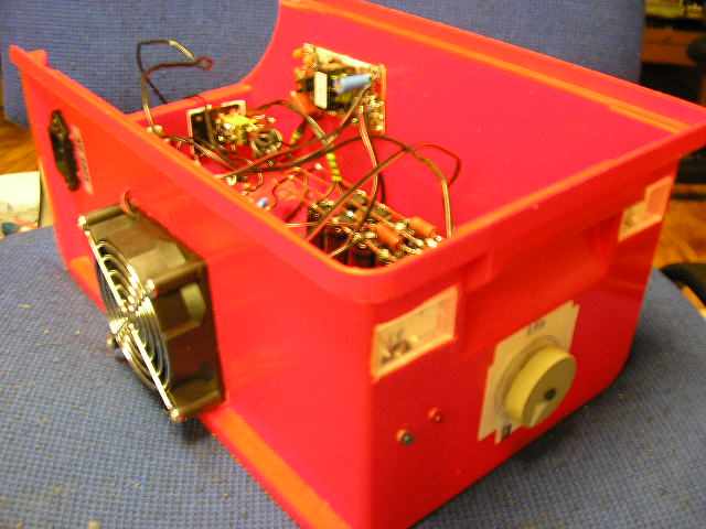
I recently made another IGBT Half Bridge.
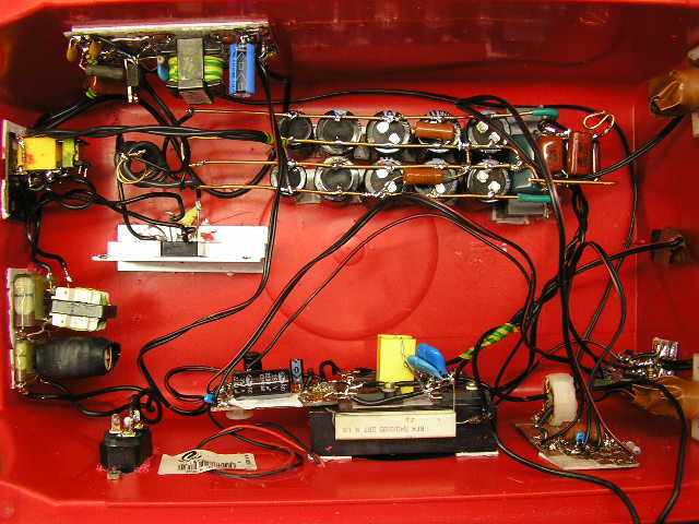
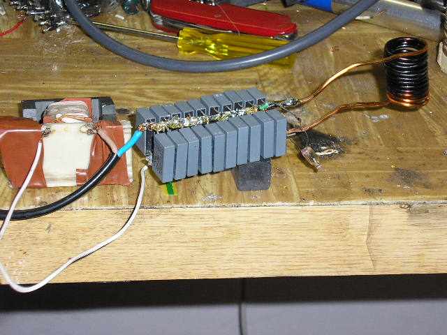
I moved to the filtered power (12x 470uF 200V pairs in series).
On power on, rectifying bridge is considerably stressed, so I
used a series resistance of about 3R3 - 6R8 5-10W, which is shortly after the turn shorted by a relay
(Relay is powered from the auxiliary power 14.5 V).
As DC blocking capacity I used 6x 2.2 uF 250VDC attached to the center of the capacitive divider
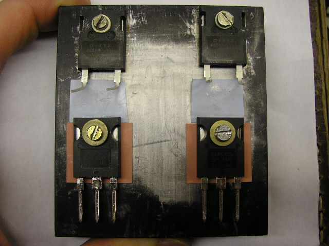
created of electrolytic capacitors. As an antiparallel diodes I used DSEI60-06A (60A 600V 35ns).
Diodes and IGBT are on a 8x8cm heatsink with fins and a fan from PC supply.
Insulating pads of IGBT's are silicon, as have a lower thermal resistance than mica. As an auxiliary power supply I used
SMPS (single blocking inverter) powered from the rectifier. Supply is similar to
this supply.
To the output I connected protective RC - serial combination of 10n capacity and resistance 3R3 10W. This serves as a snubber, which
protects the halfbridge before the volgate spikes produced by the inductive load. The capacitor is composed of four pieces due to a large stress and reliability.
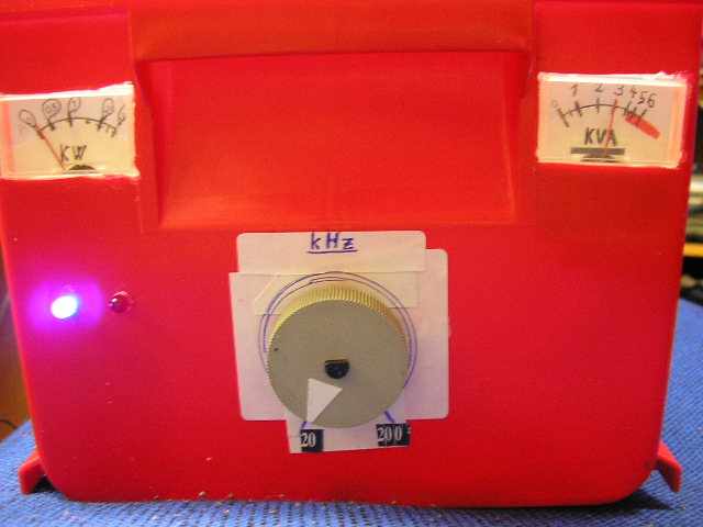
I also included Analog meters for measurement of active and reactive power. Another improvement is the
overcurrent protection, which switches the entire halfbridge off when exceeding the output power of about 4500 VA. The halfbridge supply can be put back into operation
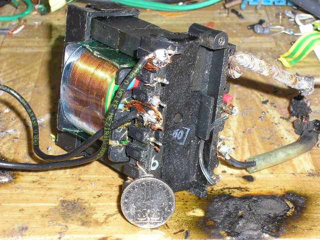
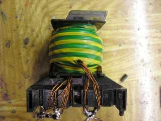
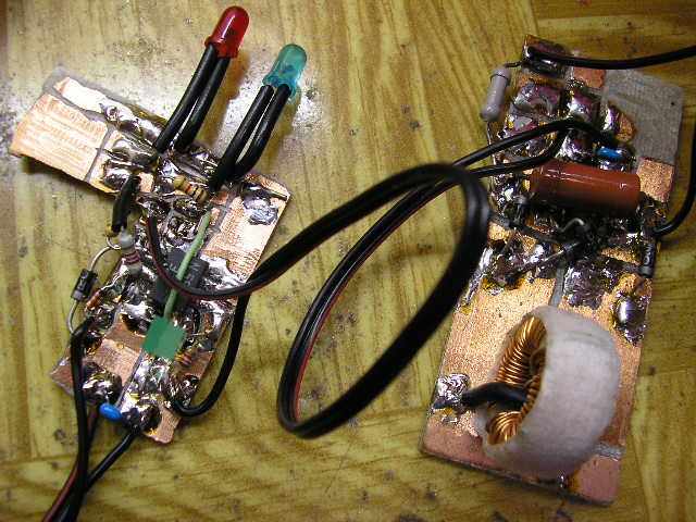
by disconnecting it from mains for a while. The current sensing is ensured by a current transformer 1:100. It is wound on a
ferrite ring (inner diameter of about 14 mm, the outer 22 mm, height 7 mm, it is not critical). The current from the secondary of the current transformer
is recrified by a bridge of fast diodes (not monolithic bridge - such bridges are designed for 50 to 60 Hz!). The circuit is measuring
voltage drop across the resistor 10R 4W. If the voltage exceeds 6.2 V (determined by zener diode 6.2 V, corresponds to the peak current
60A). Overload condition makes the output of 555 circuit turn to logical
0. When the voltage of IR2153 pin 3 drops below 1.8 V, it goes into shutdown mode and both outputs are at
zero voltage. Operating frequency of this halfbridge can be set using the potentiometer in the range of 20 - 200kHz.
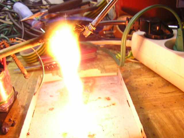
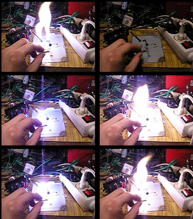
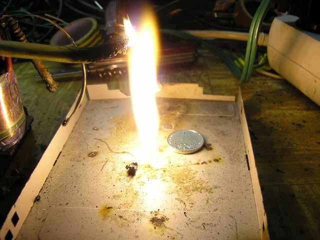
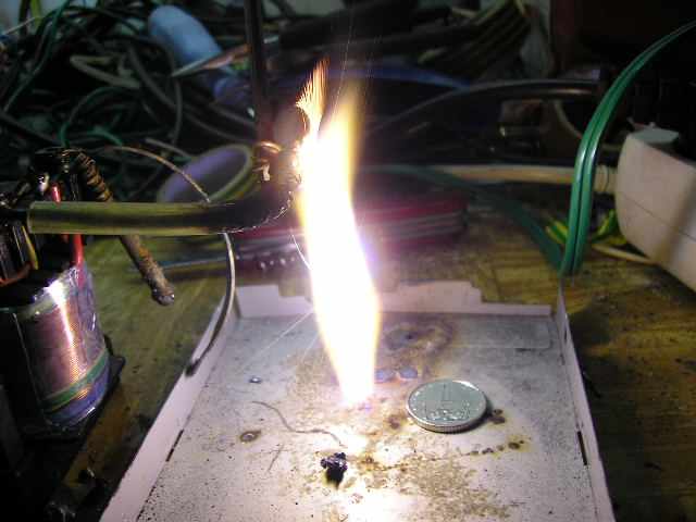
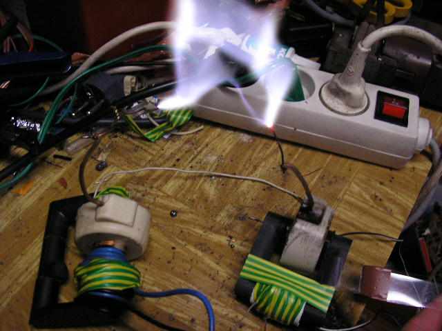
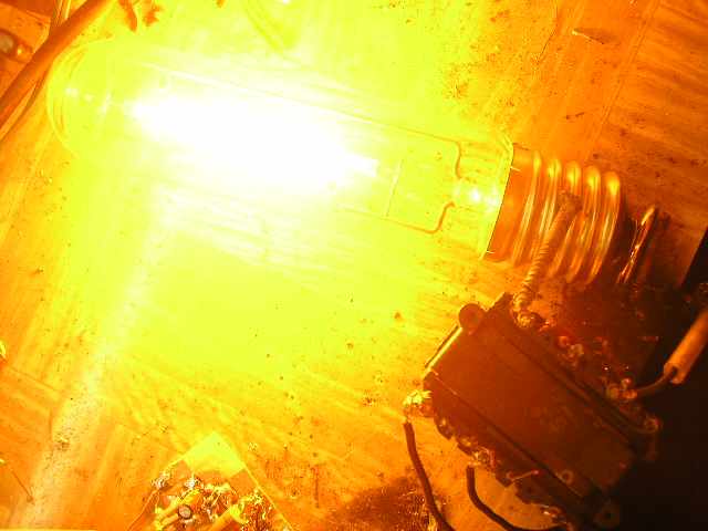
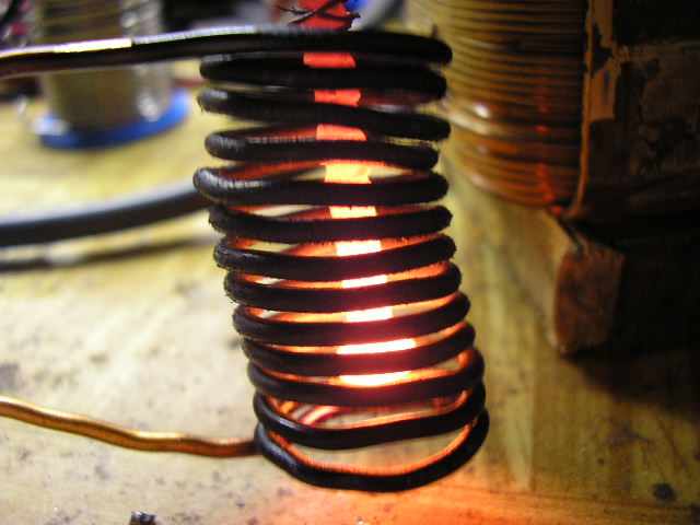
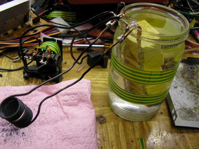
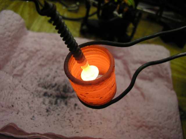
This frequency converter power supply is suitable for numerous different applications. Such as an effective transformation of any voltage using ferrite
transformers, power induction heating or transistor Tesla coil - SSTC.