The principle of induction heating is simple. Coil generates high frequency magnetic field and the metal object in the middle of
the coil induces eddy currents that heat it. In parallel with the coil is plugged resonance capacity to compensate its
inductive nature. Resonance circuit (coil-capacitor) must be driven at its resonant frequency. Excitation current is much smaller
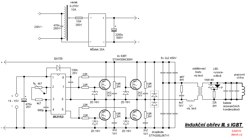
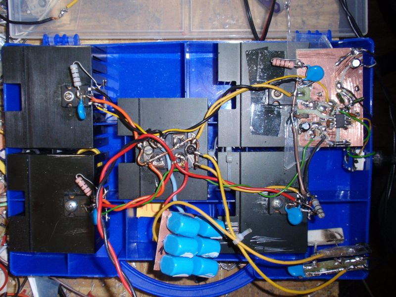
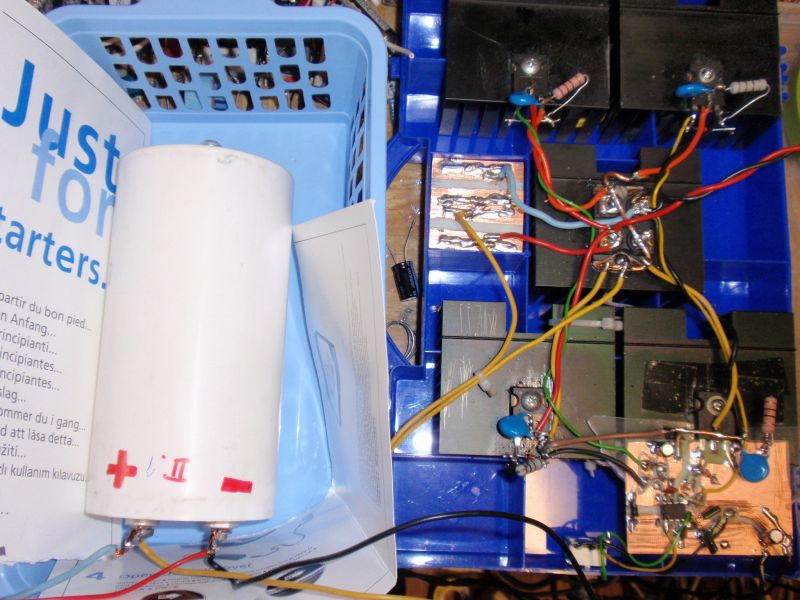
than the current, which flows through the coil. The circuit works as a "double halfbridge" with four IGBT STGW30NC60W controlled using
circuit IR2153. Double halfbridge is able to deliver the same power as full bridge, but the gate driver is simpler. Big double diode
STTH200L06TV1 (2x 120A) works as antiparallel diodes. Much smaller diodes (30A) will be enough. If you use the IGBT with built-in
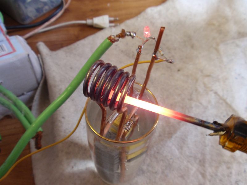
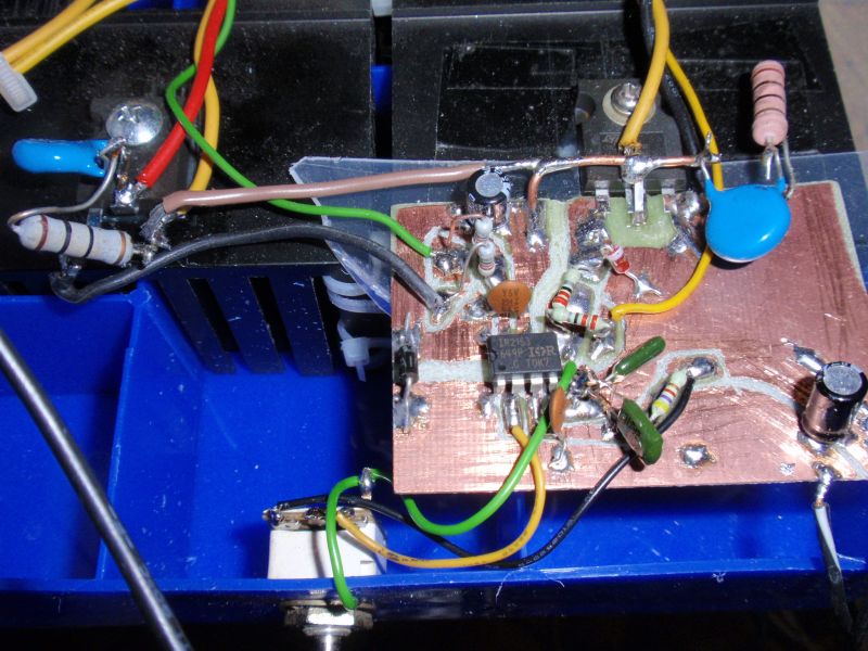
diodes (eg STGW30NC60WD), you won't have to use them. Operating frequency is tuned into resonance using potentiometer. The resonance is indicated by the
highest brightness of LED. You can of course build the more sophisticated driver. The best thing would be to use the automatic tuning,
which is course in professional heaters, but the circuit will lose its attractive simplicity. Frequency can be controlled in the range of about
110 to 210 kHz. Control circuit requires auxiliary voltage 14-15V from a little adapter (can be either switched or conventional). The output is connected
to the working circuit via
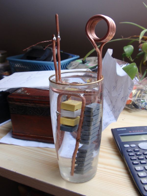
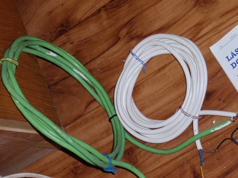
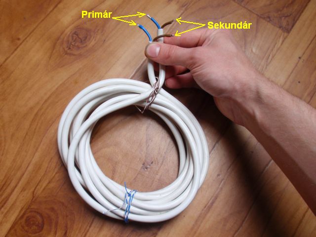
matching Choke L1 and isolating transformer. Both of them are in the air design. Choke has 4 turns on 23cm diameter, isolating transformer
is made up of 12 turns of double wired cable on 14 cm diameter (see photo below). Output power is now around 1600W and still there
is room for improvement.
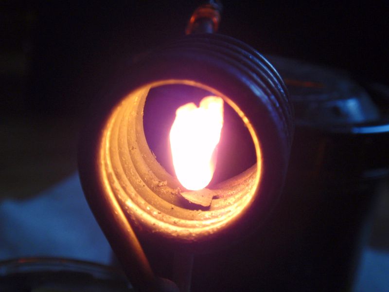
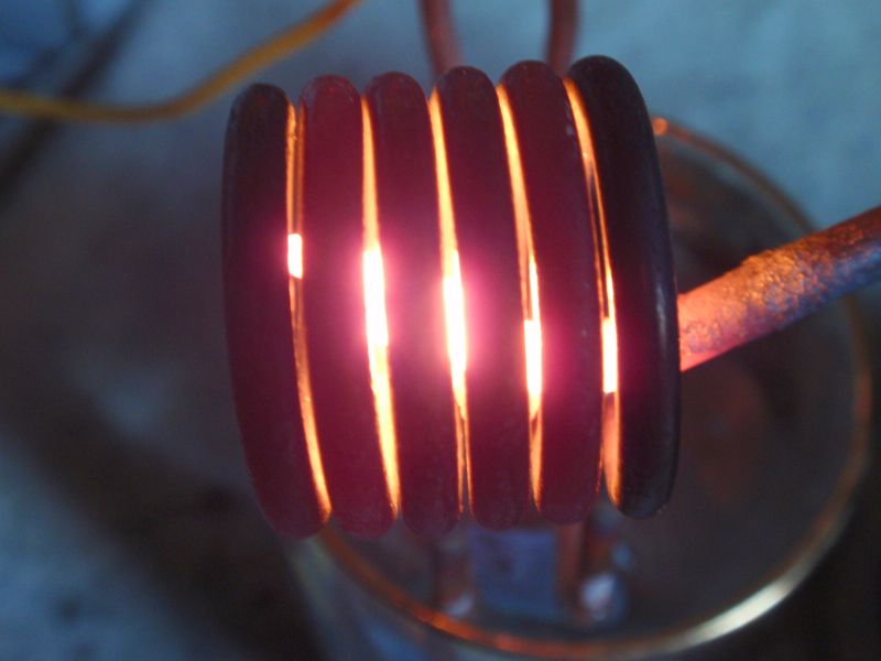
The work coil is made of wire dia 3.3 mm. Better would be a copper pipe, that may be connected to the water cooling. Coil has
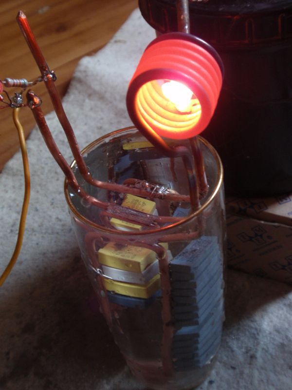
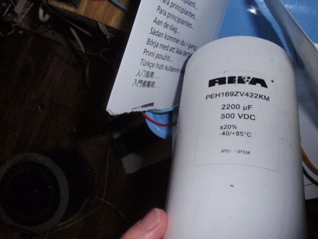
6 turns, diameter 24 mm and 23 mm height. Coil after prolonged operation gets hot. Resonance capacitor is made of
23 pcs od little capacitors with the total capacity 2u3. 100nF capacitors can be used in design (~ 275V MKP polypropylene and
class X2). They are not intended for such purposes, but can be used. Resonant frequency is 160kHz. It is recommended
to use EMI filter. Variac can be replaced by soft start. I recommend to use
current limiter connected in series with the mains (such as heaters, halogen lamps, about 1kW) when turning on for the first time.