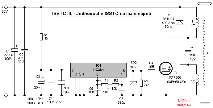
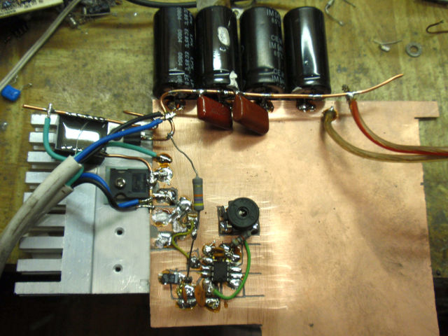
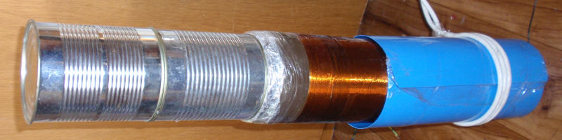
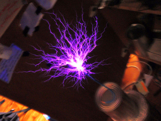
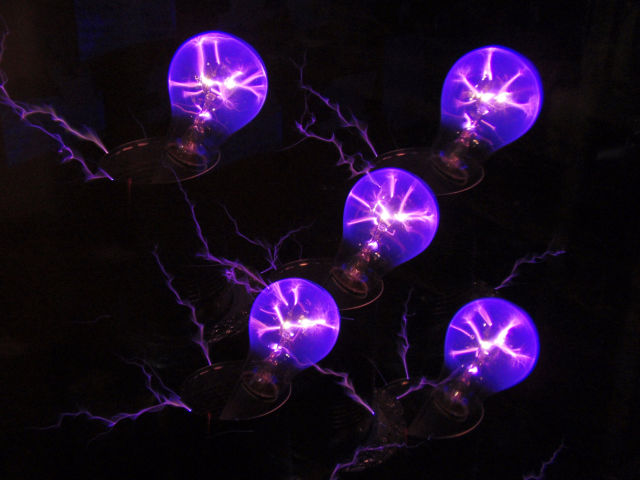
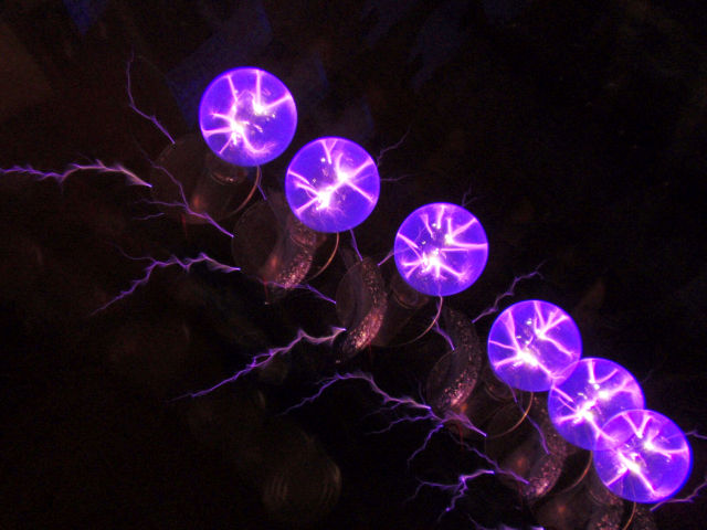
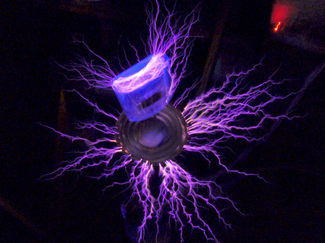
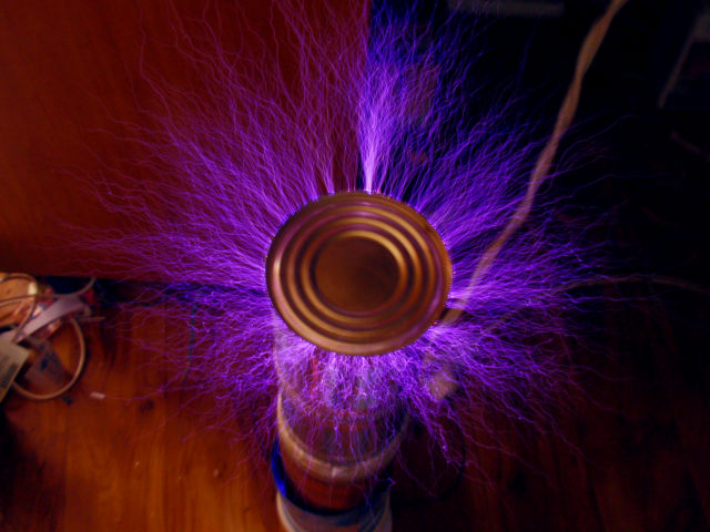
The goal of the experiment was to create a very simple SSTC - solid state (transistor) Tesla coil with interrupter, that won't be ashamed for his sparks :). Finally i made this ISSTC (Interrupterd SSTC) controlled by integrated circuit UC3844. The circuit provides both oscillator at the resonant frequency of the secondary as well as interruptions. Interruption is provided by the UVLO with hysteresis. C3 is always charged to the 16V, then IO1 turns on and, starts to oscillate and controls T1. Because current consumption IO1 is greater than the current through R1, the C3 is gradually discharged to 10V when IO1 turns off. C3 is charged again and the cycle repeats. The speciality of this SSTC is, that it operates with single transistor. In this TC, I used the secondary (winding III.) with a diameter of 108 mm and length 375 mm, wire diameter 0.2 mm. Resonance without capacity is 204kHz, resonance with two cans on top is about 150-160kHz. The resistance of wire is about 300R. Integrated circuit UC3844 (here is the datasheet) and another datasheet here is similar to the well-known UC3842, but its duty cycle is limited to 50% by by allowing the output to be high only during every other oscillator cycle. Operating frequency is set by P1 to resonance. Tuning range with these components is about 100-200kHz. It can be shifted by changing P1, R2 or C6. Interrupt frequency can be influenced by changing C3. Both interruption frequency and interruption duty cycle is also affcted the R1. With R1 = 15k and C3 = 10uF frequency is around 40Hz, with the 100uF it is 4Hz. T1 is a power mosfet IRFP260, IXFH50N20 or simillar 200V N-type MOSFET with RDS (on) below 55mR and the same or better parameters. The smaller resistance Rds(on) the better. D1 is any ultrafast diode above 200V, 8A, and preferably under 50ns. The T1 and D1 must be rated to more than 2x supply voltage (practicly about 3x od more). The circuit can be modified for other voltages by changing the number of turns I and II., R1, C1, C7 and possibly using a different T1 and D1. The transistor T1 and diode D1 are on the heatsink. Most heat of the heatsink is a power loss of T1. Primary is double due to need of resetting. This is necessary because it is a single acting circuit. It is made of power 3-wire cable. The main winding consists of two parallel wires and auxiliary winding II. is made up of third wire. Primary is wound on an insulating tube that has a diameter of 14 cm and is located approximately 5 cm above the beginning of secondary (in higher position there's threat of arcover between the primary and secondary). The C7 is pulse capacitor ensures removal of the stray inductance between the windings I and II., which is necessary to protect T1 against spikes. Streamers in the air are 16 cm and arcs to grounded electrode 20 cm. The device is operated from a supply up to 60V DC (relatively safe voltage). It draws 1.5A (power is 90W). The interrupter allows long sparks at relatively low power input.