I needed a simple oscilloscope for basic measurements and I did not want to buy it, so
I decided to build it. To make my scope simple and nostaligic style, I decided to use vacuum tubes.
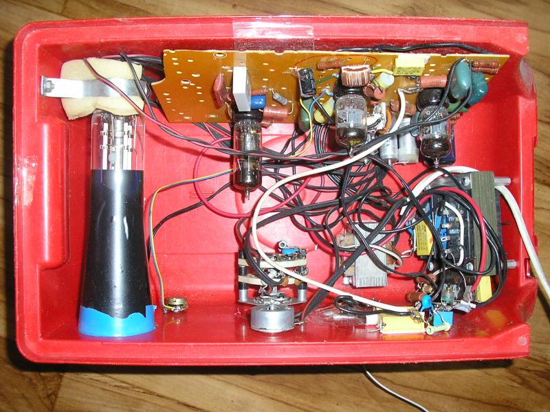
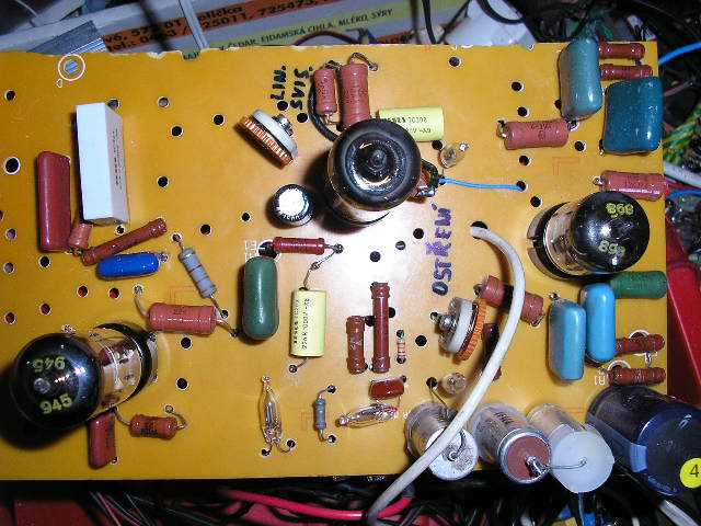
As a saw tooth (X) oscillator I am using RF pentode EF80 (fantastron connection). As a symmetrical driver of
X and Y plates I used a double RF triode 6CC42. The second tube 6CC42 serves as a two-stage amplifier (Y).
Unbalanced deflection would be even simpler, but it causes poor sharpness of the line (it would be impossible to focus
the bean on entire screen, but only on part of it). That's why I chose symmetrical deflection.
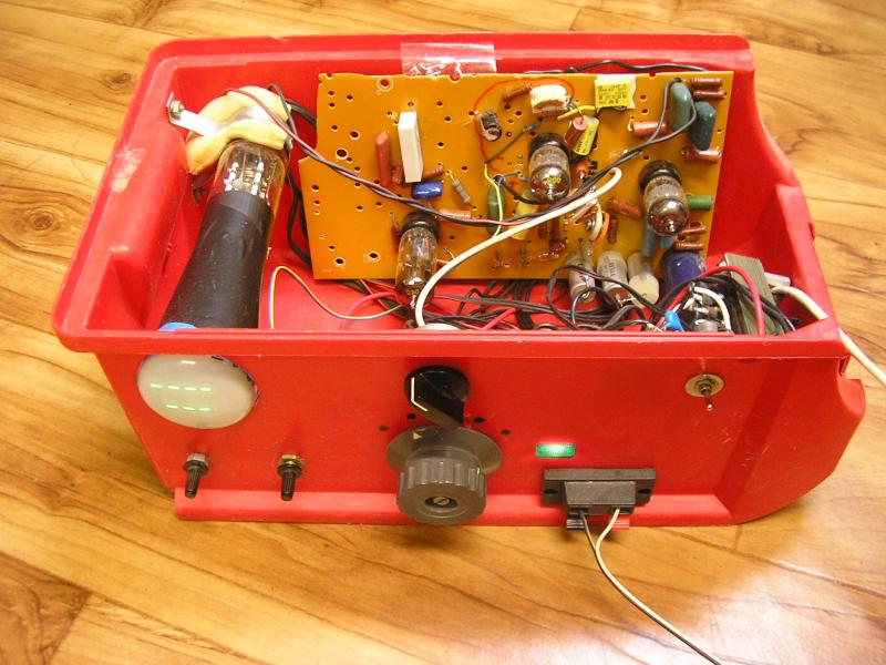
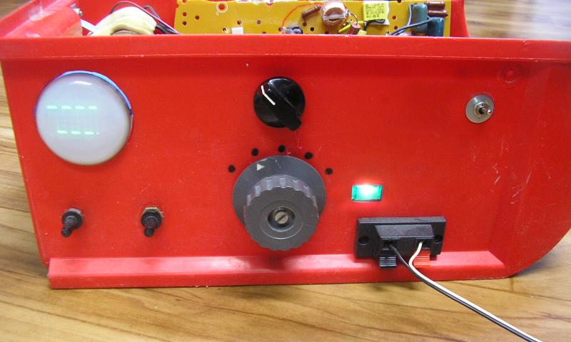
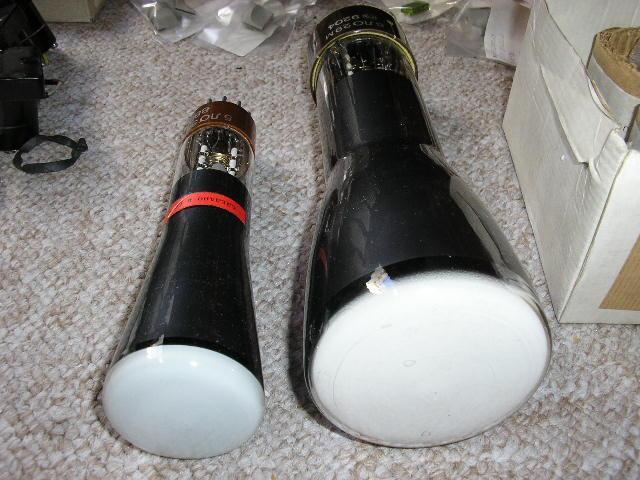
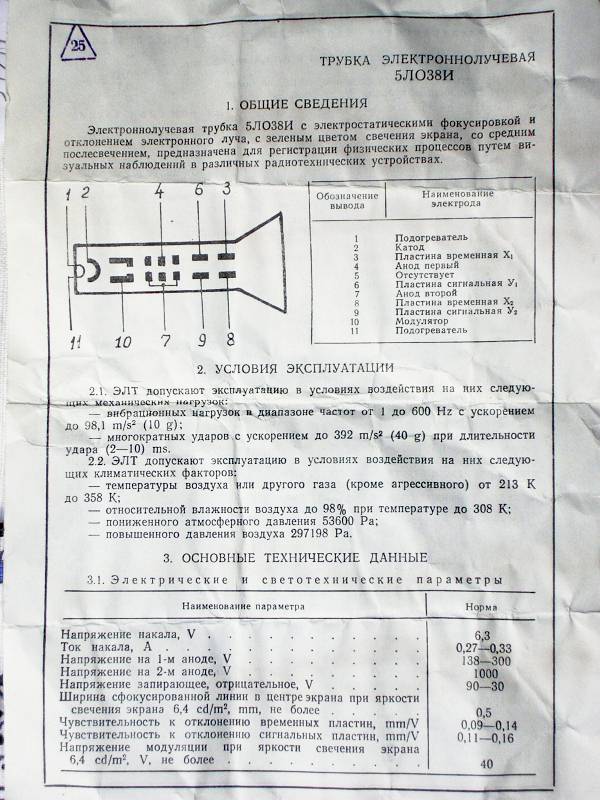
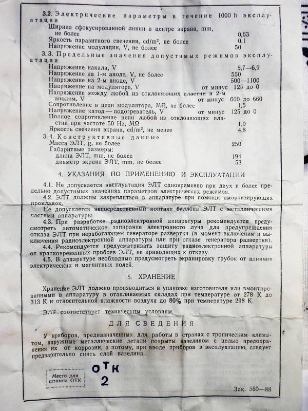
The screen is old but unused, made in the Soviet Union (USSR). Type is 5LO38I, screen diameter 5 cm, length 19.5 cm.
300V for vacuum tubes is obtained from a one-way rectifying the power transformer secondary (240V),
negative voltage of about 650V is obtained by doubling the secondary voltage. The oscilloscope has 5 ranges, which are selected by double 5-way switch.
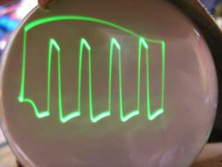
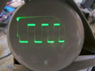
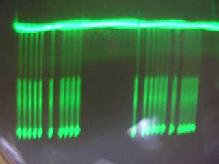
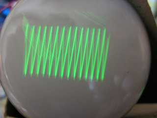
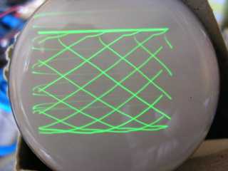
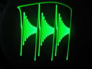
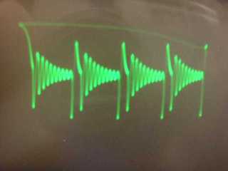
The time base is about 100ms to 4us (frequency of X deflection approx 10Hz to 250kHz). Response time is about 2us. The sensitivity is set coarse using switch
(2 steps - 1/1 and 1/20) and continuously using potentiometer in the cathode.
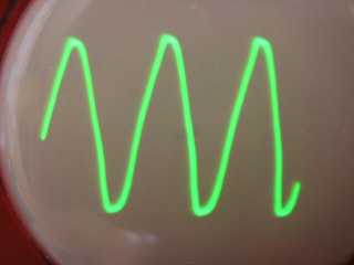
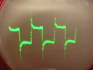
Trimmer capacitor is used to compensate the capacity (necessary for higher frequencies). It must be set so that
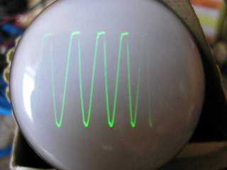
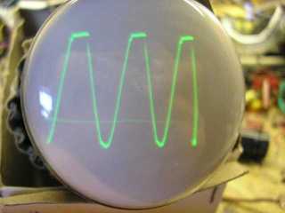
a square wave displays really as a square wave (only takes effect whwn the position of the sensitivity switch is 1/20). Maximum sensitivity is about 0.2 W / cm.
Control elements are only brightness, range, X-frequency, sensitivity and focus.
Heater of CRT and EF80 tube is rated 6.3 V 0.3 A. Heater of tubes 6CC42 is 6.3 V 0.35 A. CRT heater supply
MUST be separated from the supply of tubes, because there is a voltage difference more than 700V!