Often we need to make one appliance automatically turned with a small delay
after turning on other appliances. For this purpose the delay switch (delay relay) in the schematic below can be used.
The delay is ensured using starter from the fluorescent lamp that includes a "bimetallic switching neon lamp"
After applying the mains voltage, the current flows through the relay (contactor) coil and R1 resistor into the starter (voltage drop at R1 is small).
After a while the starter contacts are connected
the relay coil gets full voltage and the relay turns on. It disconnects the resistor R1 and shorts the
starter, making the relay permanently on. The second relay contact turns on the load (appliance).
Resistance of R1 affects the delay time. It's 0.5 - 1s for 1k. A smaller resistance value means
less time, minimum is about 330R. Increased resistance means longer time (too much resistance could cause
that the relay never turns on).
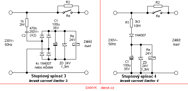
The principle of the inrush current limiter (switch on surge limiter), which limits the current surge of appliances when being turned on.
Some loads such as large motors, transformers or capacitors must have the inrush current
limited. This can be done by switching in two stages. First,
inrush current limiter connects the load to the mains via R2 (it may be power resistor, inductor, light bulb ...)
and after a delay the R2 is shorted by relay contact Re1b.
On the schematic diagrams below are two simple two-step inrush current limiters.
The first version turns on regardless of the state of the load. R2 may be undersized as
is used only briefly.
The second version works with conditional switching. If there was a short circuit on the load or overload,
output voltage is not large enough and relay won't turn on. In the second version R2 must be
rated for continuous operation or protected by (thermal) fuse.
Version 3 and 4 is using a single contact relay contact and 24V coil, which may be easier to find.
The time delay can be affected by the value of the capacitor C1.
The schematic is suitable for relays with current up to 30mA, therefore the resistance of the coil over 800R.
In version 3, the line voltage is limited capacitively by capacitor C2 - 470n/250V~.
Capacitor C2 determines the current through the relay coil. If the circuit is not permanently connected to load, to ensure
its discharge after switching off, it is advisable to connect parallel resistance approx 1M/1W.
In version 4 the line voltage is limited usind resistor R1. The wiring is simpler than the previous version,
but the drawback is a big loss at R1 (around 7W). Version 4 is inspired
by Professor 700W microwave oven.