This simple tester can test bipolar NPN and PNP transistors,
but also other semiconductors and passive components such as MOSFETs, diodes, triacs, thyristors (SCRs), LEDs, switches, etc.
You can also check the leakage current of capacitors. Using this tester is very simple.
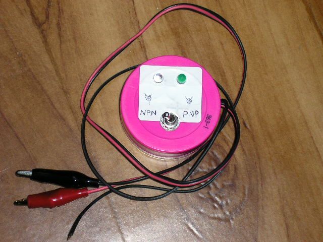
The working pinciple of this tester is apparent from the schematic diagram. The LEDs (any type, but brighter is better) are used as
indicators of current between the "+" and "-" terminals. LED 1 is connected through a transistor, so it sensitively indicates
even a small current. LED 2 indicates a higher current. The switch connects the base (gate) of a transistor to a positive or negative voltage via a 47k resistor.
A power switch is not necessary if the terminals don't touch each other when the tester isn't in use.
• NPN/PNP bipolar transistors:
For an NPN transistor, connect the collector to the "+" terminal and the emitter to "-". The switch is set to "NPN".
At this moment no LED is lit. Then connect terminal B to the base, both LEDs should light up.
PNP transistor is tested similarly, but the switch is switched to "PNP", emitter is "+" and collector is "-".
If you connected the emitter and collector the other way, the green LED lights up dimmer.
• FETs, MOSFETs (unipolar transistors):
For N-type connect D (drain) to "+", S (source) to "-" and G (gate) to "B". When switching to "NPN" position, both LEDs are lit, in "PNP" position no LED is lit.
For P-type the S is connected to "+" and D to "-". The switch works the opposite way (the PNP position lights up the LEDs).
• Thyristors (SCRs):
For thyristors, only terminals "+" and "-" are used. The anode is connected to the "+" and cathode to "-". No LED is lit now.
For PNPN type connect G with "+" momentarily, both LEDs should light up and stay on even after disconnecting G from "+". In NPNP (rather
unusual type of thyristor) connect G with "-", everything else is the same. (Note: the test current may not be enough to hold bigger thyristors in ON state.)
• Triacs:
Testing triacs is similar to the SCRs, but it is tested in both directions and in all 3 or 4 quadrants (according to the type of the triac).
• Diodes:
Anode is connected to "+" and cathode to "-", both LEDs lit. In Reverse no LED is lit.
• LEDs:
Anode is connected to "+" and cathode to "-", both LEDs in the tester and the LED under test will light up.
• Testing bulbs, switches, buttons, coils, cables, connectors:
Use the terminals "+" and "-" to test the conductivity of
the filament of tungsten light bulbs, switches, buttons, coils, cable or connector.
Terminals "+" and "-" are used simply as a conductivity tester for anything.
• Capacitors:
The capacitor is connected to the "+" and "-" and after it is charged, no LED is lit, otherwise the capacitor is short or has
a high leakage current. Bigger capacitances may take long time to charge, it will take longer time before the LEDs will turn off.
For electrolytic and other polar capacitors (tantalum) you have to observe the polarity!
• Speakers and headphones:
Connect the speaker or headphones to "+" and "-". The LEDs will light up and you will hear a click sound in the speaker/headphone.