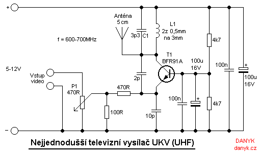
This simple homemade television transmitter allows you to broadcast TV picture on the UHF band 470-855 MHz.
The frequency is determined by the values of components L1 and C1. The values given in the schematic diagram set the transmitter
to about 600-700 MHz, that is in the range of 37. - 50. channel of analogue TV bands.
The television transmitter consists of a simple oscillator with high frequency NPN transistor.
Suitable are for example BFR90, BFR91A, BFR92 or BFR93. I used BFR91A
in the planar to50 case. Its transition frequency is 6GHz. Carrier frequency
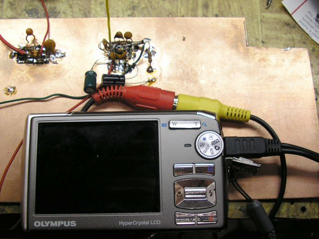
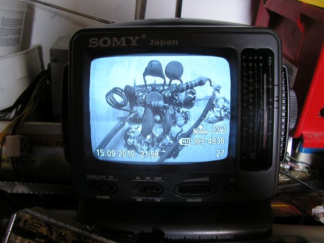
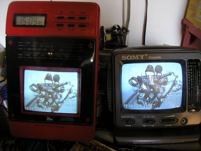
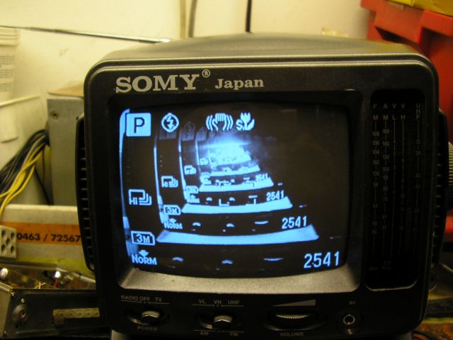
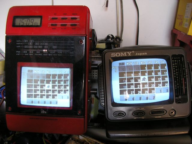
is amplitude-modulated by the input video signal. As the video source you can use
a security TV camera or camera with video output.
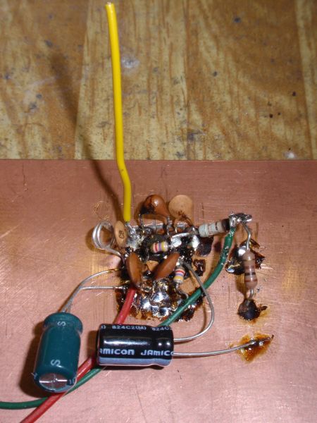
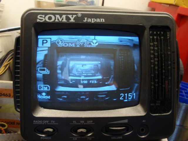
Antenna is about 5cm (2'') of wire and is connected directly to the oscillator. The transmitted signal can be
tuned on any analog TV with UHF band. Operating frequency can affect by changing
values of L1 and C1. Fine tuning is possible by stretching or shrinking turns of L1. The television transmitter needs a supply of voltage
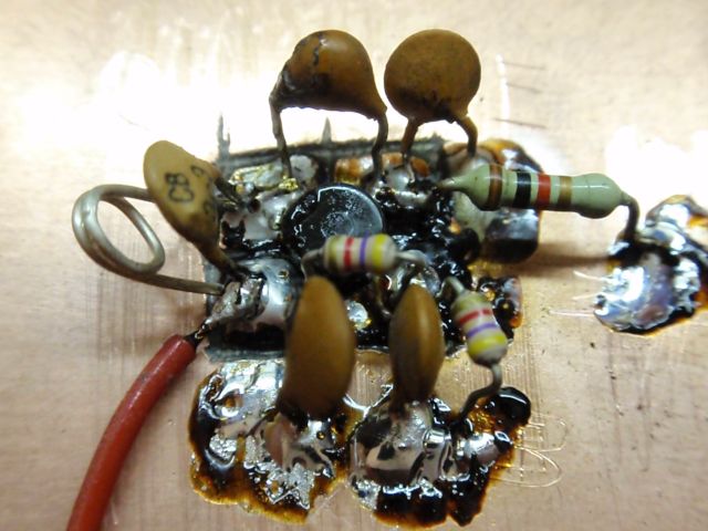
about 5 - 12V. All live connections should be shortest due to parasitic
capacity and inductance. Decoupling capacitors 100n should be as close as possible to the transistor.
The electrolytes 100uF are in parallel to them, because it is necessary to effectively block
frequencies from 50 Hz up to hundreds of MHz. Potentiometer P1 sets the modulation depth.
Set it so that the image quality is good. Too deep modulation leads to too much contrast.
At too low modulation level the image has low contrast and the vertical and horizontal synchronization may fail.
The television transmitter can transmit any signal, for example PAL (50Hz) or NTSC (60Hz), important is what your
television can display.
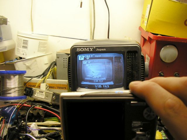
Tuning: Turn on the transmitter, connect the video source and search on an analog TV.
Look for it around the 600-700 MHz or 37 - 50 channel.
Some TVs with auto-tuning can skip the videosignal with no audio, so it is better to search manually.
| Table of analog UHF TV band channels and frequencies | |||||||||
| channel frequency (MHz) | |||||||||
|
21. 471,25 |
22. 479,25 |
23. 487,25 |
24. 495,25 |
25. 503,25 |
26. 511,25 |
27. 519,25 |
28. 527,25 |
29. 535,25 |
30. 543,25 |
|
31. 551,25 |
32. 559,25 |
33. 567,25 |
34. 575,25 |
35. 583,25 |
36. 591,25 |
37. 599,25 |
38. 607,25 |
39. 615,25 |
40. 623,25 |
|
41. 631,25 |
42. 639,25 |
43. 647,25 |
44. 655,25 |
45. 663,25 |
46. 671,25 |
47. 679,25 |
48. 687,25 |
49. 695,25 |
50. 703,25 |
|
51. 711,25 |
52. 719,25 |
53. 727,25 |
54. 735,25 |
55. 743,25 |
56. 751,25 |
57. 759,25 |
58. 767,25 |
59. 775,25 |
60. 783,25 |
|
61. 791,25 |
62. 799,25 |
63. 807,25 |
64. 815,25 |
65. 823,25 |
66. 831,25 |
67. 839,25 |
68. 847,25 |
69. 855,25 | . |