Introduction:
Wattmeter is an important measuring instrument. It allows to measure the true electric power (Wattage).
Determining the true power in AC circuits cannot be made simply by multiplying the RMS voltage and current because the
power factor is often not equal to 1. You must use a meter that continuously measures
instantaneous current and voltage, multiplies them and produces an average value. Analog electromechanical devices do that
using a current coil (solid) and voltage coil (moving, with a needle attached to it). The magnetic force acting between the coils is equal to the product
of magnetic fields. Averaging is achieved by the momentum of the system. Traditional analog scale wattmeters aren't very accurate and usually have a low useful measuring range.
Electronic wattmeter theory:
I decided to make it solid state way - to build an electronic power meter with analog processing and digital reading.
Display is provided by a digital multimeter, which can now be bought under 100 CZK (roughly 4 USD), and therefore it does not make sense to build your own
digital voltmeter. It is also possible to use panel digital voltmeter or even an analog meter.
Immediate voltage is sensed using a voltage divider. The current is sensed by a shunt. The voltage and current are then multiplied by an analog multiplier AD633.
The output provides a voltage proportional to the instantaneous power. To obtain the average power it is necessary to filter the signal using an RC filter.
The biggest challenge in this design is generating the product of two analog voltages. This is not as simple as it
might seem. There's a possibility of multiplication using operational amplifiers and junctions of discrete diodes or transistors, which have an exponential characteristic.
Their principle is to logarithm both signals, add them and finally de-logarithm them. Accuracy is not too good, there are problems with calibration, a huge
temperature dependence and differences between individual pieces of transistors or diodes. That's why I rejected this option. Another option is
using pulse-width multipliers, but this solution is also quite peculiar. Even more complications occur when it is necessary to work
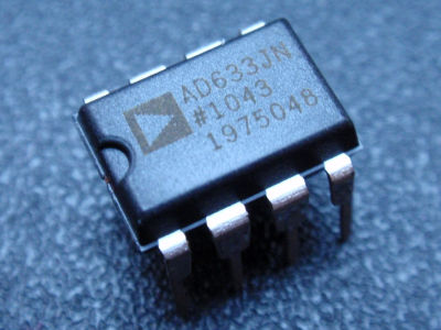
with both polarities of current and voltage (4 quadrants). So I decided to use a specialized integrated circuit AD633 (AD633JN in classical THT case DIP8) -
a four-quadrant analog multiplier with differential inputs and precision of 2%. For more info see AD633 datasheet.
Note that SMD version has a different pinout!
The output voltage is given by a formula:
w = (x2-x1) * (y1-y2): 10V + z
I wanted to try an integrated circuit MPY634 with an accuracy of 0.5%, but I couldn't find one.
Maximum input and output voltage range at which the circuit AD633 operates is +/- 10V. This must match both the input voltages.
The circuit must be designed to the amplitude of current and voltage, not only an effective value. For 230V mains, you have to work
with 325V peak, not only 230V. A divider ratio of 1:40 seems to be the best. This allows you to work with peak voltage up to 400V.
Shunt voltage is lower than the voltage of voltage divider, so is connected to the input Y, which has better accuracy.
Simple Wattmeter circuit:
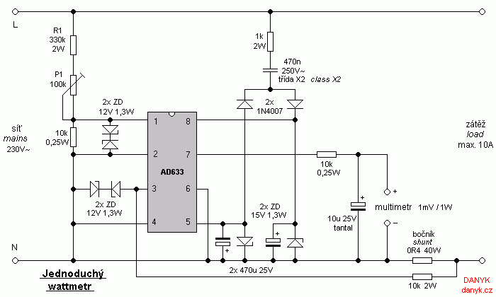
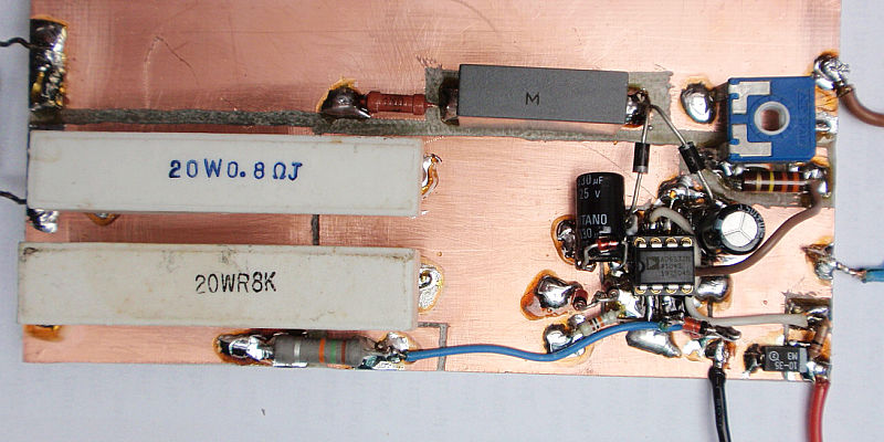
Fig. 1 is the simplest power meter (wattmeter) design with the AD633 and a single range.
The current is sensed by a shunt. If we require the output signal conversion 1mV/1W, the value of the shunt should be
0R4 (0.4 ohm). Maximum RMS current through meter is determined by the maximum allowable shunt power dissipation.
For 0.4 ohm 40W shunt the max continuous current is 10A. Maximum measured power is 2300W for ideal resistive load, for different loads it must be lower.
Another limitation is the maximum input voltage of multiplier (10V),
so the maximum peak current must be below 25A.
Calibration is done by setting P1 according to a known load. The sum of the values of P1 and R1 will be about 390k and the dividing ratio will then be 1:40.
If you can't set the correct value using P1, change R1 value. Multiplier inputs are protected against overvoltage by 12V zener diodes.
Supply voltage (+/- 15V) is obtained using a capacitive dropper and two 15V Zener diodes.
In combination with a multimeter with 0.1 mV resolution you will get a wattmeter with 0.1 W resolution. We will use
200mV, 2V and maybe 20V ranges where the power
is displayed directly in watts (1mV = 1W) or kilowatts (1V = 1kW).