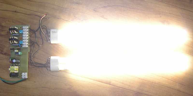
I developed a simple and inexpensive electronic ballast
for one or more fluorescent lamps with total power up to 144W.
Electronic ballast has a much higher efficiency than a conventional magnetic ballast, eliminates the stroboscopic effect and blinking,
allows fast start with no flicker and extends the life of fluorescent lamps. Also it eliminates the use of glow starters and problems with compensation
of phase shift.
Moreover, high-frequency excited fluorescent tube has about 10% more light output at the same power.
Comparison of their traditional power inductors
and electronic ballast for typical lamps shown below:
| FLUORESCENT TUBES | 18W | 2x 18W | 3x 18W | 4x 18W | 36W | 2x 36W | 3x 36W | 4x 36W | 58W | 2x 58W |
| Conventional (magnetic) ballast self consumption | 9W | 18W | 27W | 36W | 9W | 18W | 27W | 36W | 13W | 26W |
| Electronic ballast self consumption | 2,5W | 2,9W | 3,5W | 4,3W | 2,8W | 3,8W | 4,9W | 6W | 3,2W | 4,2W |
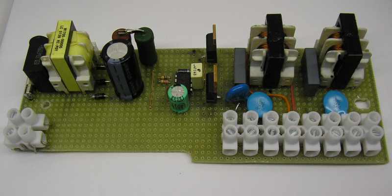
Circuit works as a halfbridge
with MOSFETs. They are driven from IR2153 integrated circuit.
Working frequency is 35kHz (ideal frequency RF excitation fluorescent lamps).
This ballast can power almost any fluorescent lamps. The values of C1 and L1 adapts to the power (ie the current)
of desired fluorescent tube. For thin fluorescent lamps (T5 size, diameter 16mm, 4 - 21W) and
Small fluorescent DZ (U-shape or 2U, 5 - 18W, without integral starter - 4-pin) can be used capacitor and choke from almost any energy
saving lamps (CFL). Capacity of starter capacitor is about 2n2 to 3n3. The converters can be connected
the broken tube-saving lamps with the original choke and starting capacitor. Output voltage
and frequency corresponds to the halfbridege used in compact fluorescent lamps (rectangular waveform
approximately 160V 35kHz). For bigger fluorescent lamps (T8 26 mm or 38 mm and large T12 fluorescent DZ, 15 - 65W, 0.38 to 0.43 A) you must
wind a coil with appropriate inductance and sufficiently dimensioned, or combine 2 to 3 chokes from CFL
in parallel. Large fluorescent lamps are rated from 0.38 to 0.43 A. The current through fluorescent lamp
can be fine-tuned by changing the inductance coils (change of air gap) or a small change in operating frequency.
Change is possible in the range of about 30 - 40 kHz and is achieved by changing the value of components in the oscillator (330p, 68k).
Starter capacitor C1, C2 is chosen to be close to resonance with the choke. For large fluorescent lamps are selected
about 10nF. After switching
there is increased voltage of around 500V, the lamp ignites. C1, C2 has to be rated 1000V.
Capacitor C3 protects MOSFETs against voltage peaks from the inductance and reduces the value of the voltage rate of rise (dU / dt). Its capacity is chosen so
to avoid hard switching (about 5 - 6nF to 1A of current to fluorescent lamps). Should be pulse,
rated 1000V.
Due to the high efficiency,
the total power into fluorescent lamps can be accurately estimated by the current, which is measured at the filter electrolyte.
The voltage here is about 300V. Subtracted own consumption ballast around 3W. The ballast can
add more lamps in parallel. Each then has its own capacitors and inductors.
Used transistors (IRF840 or STP9NK50Z) do not need to have heatsink up to 72W of output power. Own consumption of the circuit
is about 2.5 - 6W (under load). Input power is connected RFI filter and thermistor
to limit peak inrush current during switching on. For low power it can be replaced by ordinary resistor.
Voltage 15V for circuit IR2153 is obtained the power resistor from the rectified mains voltage 300V. Zener diode is not
needed - that is already built in IO (Uz = 15V). Precipitation resistance
33k has a loss of about 2.3 watts and is the largest dissipator in the circuit. But the loss of ballast is nevertheless
much smaller than when using conventional inductors. (If you want to get rid of this dissipation,
you can use a micropower startup resistor of about 1M and derive the power for IR2153 from the output of the
halfbridge via a little capacitor, like it is done in most of electronic ballasts.)
The capacitance of the filter electrolyte capacitor depends on the power of the lamps. It is calculated about 0.3 - 1uF per Watt.