I recommend the newer version -
Battery analyzer 2.
Introduction:
This simple device allows you to measure the capacity of an accumulator or rechargeable battery (measured in mAh / Ah) and discharge energy (in Wh).
It is suitable for NiCd and NiMH cells and accu-packs (1-12 cells), lead acid (flooded, VRLA, SLA) batteries up to 12V, Li-Ion and Li-Pol
(1-4 cells), but also for other types such as LiFePO4, NiZn, alkaline, etc., with a total voltage of up to 20V. Discharge current can be selected from 0.01 to 2.56 A.
This will allow you for example to check the the health of the battery, the efficiency of the charging method
or to detect counterfeit batteries (the market is flooded with those in recent years).
It also allows the maintenance of the battery by discharging it down to the required voltage prior to charging or to discharge the battery
to a suitable voltage to prepare it for a long storage.
You can even measure the capacity of a single use (disposable) batteries, but those become useless after the measurement.
Description:
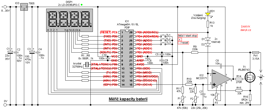
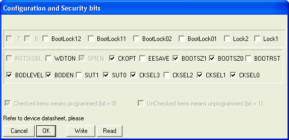
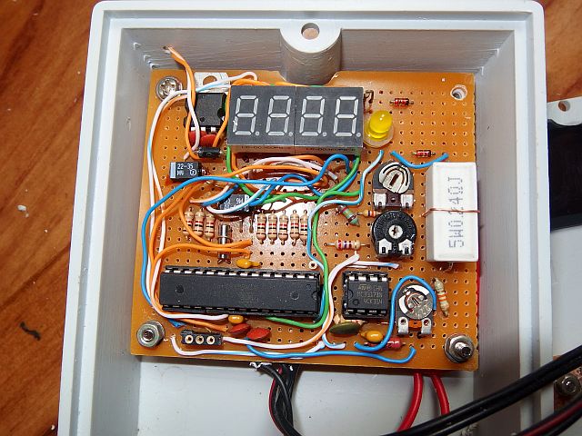
The hearth of this battery analyzer (capacity meter) is microprocessor IO1 - Atmel AVR ATmega8A, ATmega8 or ATmega8L. Program to download and configuration bits setting is below.
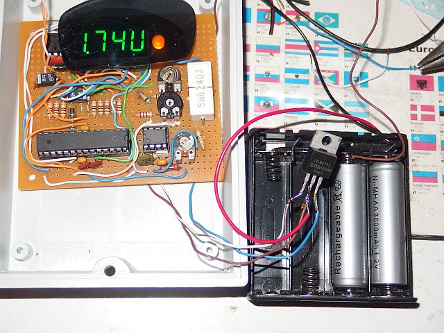
The working principle is simple: Connect the fully charged battery to the capacity meter. The battery is discharged via the meter and it determines its capacity and energy.
The discharge current can be digitally selected in the range of 0.01 to 2.56 A in steps of 0.01 A.
Discharge is terminated when reaching the end voltage (cut-off voltage), which is also
digitally selectable. IO1 is clocked by an internal 8 MHz RC oscillator. Because the accuracy of the measurement depends on the time measurement, 32 768 Hz timing crystal is used.
Battery voltage (20V maximum value) is sensed by a divider with R9, R11, P1. Adjust the trimmer P1 so that the value on the display (in actual voltage display mode)
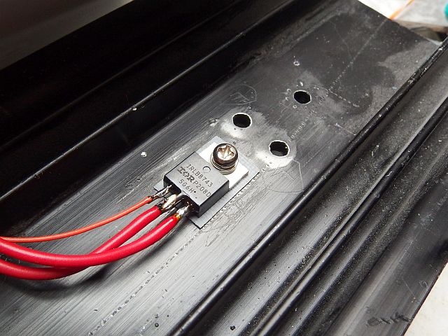
equals the real voltage. The battery is discharged through the transistor T1 (IRLB8743). The discharge current is sensed by shunt resistor R16 (0.24 ohm).
The discharge current is stabilized by an operational amplifier (OpAmp) IO2. The reference voltage is obtained by pulse width modulation (PWM) from the terminal
OC1A (PB1 - pin 15) of integrated circuit IO1. The PWM signal passes through the resistive divider and the low pass filter R10, R12, P2 and C7 and this produces a DC voltage proportional
to the desired discharging current.
Voltage on the gate of T1 is then controlled by IO2 integrated circuit so that the voltage at the shunt R16 corresponds to this reference voltage.
Current callibration process: Set P3 to center position. Connect a battery capable of at least 2.56 A discharge current and a current meter in series with it.
Set the desired discharge current to 2.56 A, start the discharge (long press of TL1 button), then
set trimmer P2 so that the actual discharge current equals to the chosen value (2.56A).
Then set the discharge current to 0.01 A. Then correct the offset of inputs of the OpAmp IO2 using P3 - set P3 so that the actual current is 0.01A.
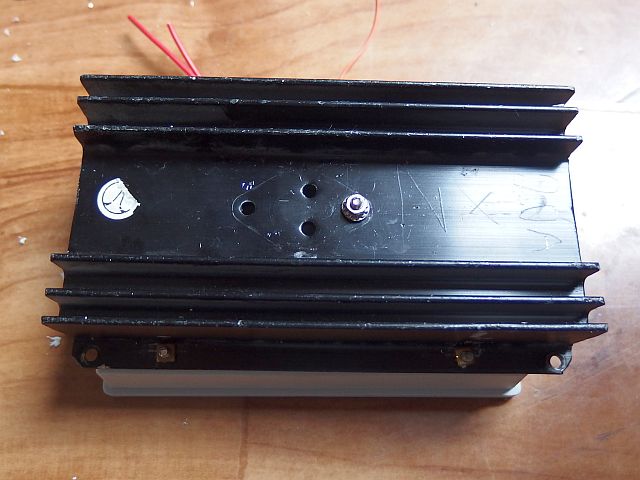
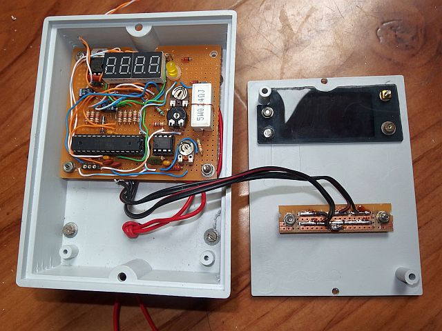
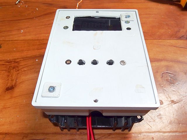
Transistor T1 is to be placed on a heat sink corresponding to the maximum necessary power dissipation during
discharge (P = U . I). T1 is a logic-MOSFET, which can operate with only 5V on its gate. If a standard type of MOSFET used, it is theoretically possible to power the IO2
integrated circuit from a higher voltage (it may be the voltage at the input of 7805), but I recommend a logic-MOSFET.
IO3 doesn't need to have a heatsink, if the supply voltage is not very high (less than cca 15V). LED1 indicates that discharge and measurement is running. Diodes D1 and D2
ensure that the T1 transistor is fully off when the discharging process is not active.
The buttons TL1 to TL3 are used to control the device. As a display device, 4-digit LED display with common anode is used. The cathodes of the display are connected to port D,
the anodes to bits 2-5 of port B.
Four-digit display can be set up as two double digit LD-D036UPG-C, LD-D028UR-C, LD-D036UR-C or LD-D056UR-C (types with very high brightness).
Superbright display allows you to omit the usual transistors to amplify the anode current. The display is controlled in multiplex.
Multiplex frequency is about 100 Hz. R1...R8 determine the display current and thus its brightness. They are chosen so that the current does
not exceed the maximum output current of the AVR pin (40 mA). Battery capacity meter is powered from a supply of about 8 - 30V.
Current requirment is about 15-45 mA, depending on the number of lit segments and values of R1... R8 (most consumed current is caused by LED display).
Capacitors C5, C6, C9 and C10 should be as close as possible to the integrated circuit IO1. In series with the tested battery, connect appropriate fuse, otherwise failure of the
capacity meter (for example failure of current control or T1 failing short circuit) or reverse polarity of battery can cause fire!
It is also recommended to use a fuse at the + power input.
Control:
The battery meter is controlled with 3 buttons: "Mode", "+" and "-". Mode button switches six display states:
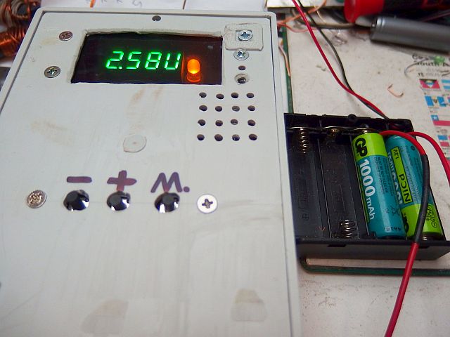
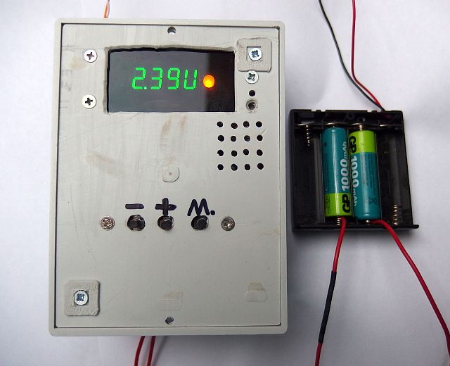
• 1) Display the actual voltage (0.00 V - 20.4 V).
• 2) Measured energy in Wh (Watt hours). Displays "En" symbol and then the value. During the discharging process it increments. After the discharge is finished, it shows the result.
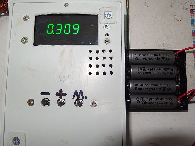
• 3) Measured capacity in Ah (Ampere hours). Displays the "Ah" symbol and then the value. During the discharging process it increments. After the discharge is finished, it shows the result.
• 4) Elapsed discharge time in hours (0.00h - 655h).
• 5) Desired discharge current. Use the + and - to select from 0.01 A to 2.56 A.
• 6) The selected end voltage. Use the + and - to select the voltage at which the discharge process is terminated (range from 0.80 V to 20.0 V).
Pressing "-" in steps 2, 3 and 4 you can reset the energy, capacity and time values (it only works if the discharge process is not active).
Long press of the Mode button starts or stops the discharging process. When discharging process is active, LED1 is on.
After the LED1 turns off, you can read the measured data (energy, capacity, time). Before a new measurement you need to reset the data.
(The data are not automatically reset at the beginning of the discharge and measurement process. This allows you to resume an interrupted measurement.)
The end voltage is usually chosen around 0.8 - 1 V for NiCd and NiMH, 2.5 - 3 V for Li-Ion and Li-Pol and 8 - 10 V for lead-acid batteries.
The program for download:
source code in Assembler (ASM)
compiled in HEX file (2154 Bytes)
How to write the program into the AVR is described here.