Introduction:
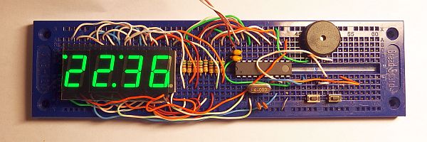
This is probably the simplest possible digital LED alarm clock.
The aim was to get as much functionality as possible into the simplest hardware, similar to one of
The simplest digital clock with AVR.
In addition to time and 3 types of alarm modes, this device can also show the date and day of the week.
It has date with leap years fix and it automatically switches to daylight saving time and back.
The brightness of the LED display is adjustable.
Description:
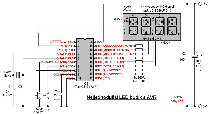
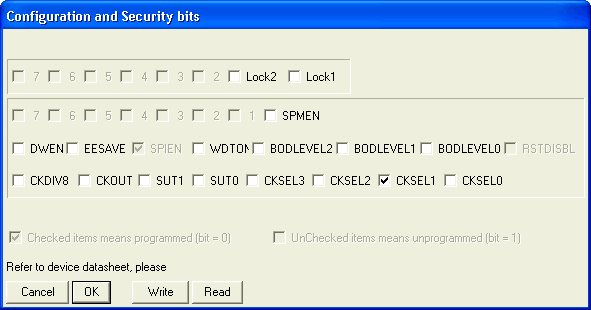
The hearth of this alarm clock is Atmel AVR microcontroller ATtiny2313A (ATTiny2313, ATTiny2313V). Program for download and configuration bits setting is available below.
It has 4-digit LED display. Cathodes of LED displays are connected to port B,
anodes to bits 0, 1, 4 and 6 of port D. Using superbright display allows you to omit the usual
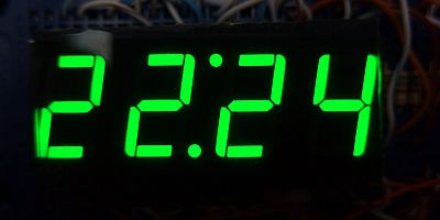
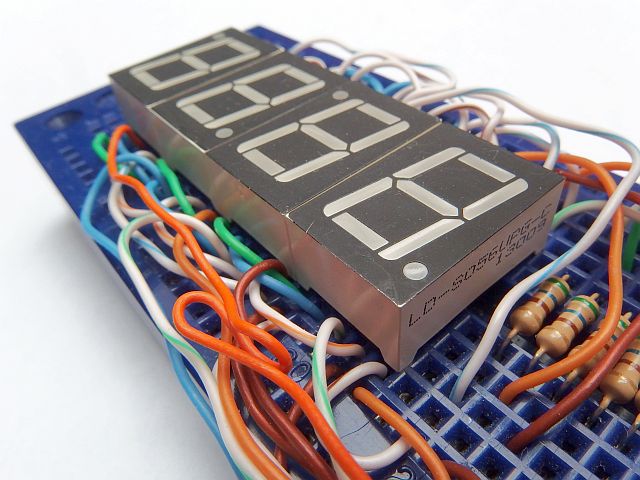
current amplifying transistors. The display is controlled by a multiplex. It consists of four one-digit seven-segment LED displays
with common anode, eg LD-S056UPG-C (14mm pure green). The second and fourth display digits are "upside down" so that the second dot
form the upper dot of colon and fourth digit dot forms the alarm indicator. Rotation of the displayed numbers is done in hardware
(Reverse segments a-d, b-e, c-f). Port PB0 thus, for example, is connected to all segments located at the top.
The clock needs a supply of about 5V. ATTiny2313 operates down to 2.7V, ATtiny2313A and ATTiny2313V down to 1.8V.
At such a low voltage the display may not work, but it could be useful when adding a backup battery.
Consupmtion at 5V is about 15 to 30 mA, depending on the number of lit segments (most of the power consumption is the LED display).
The clock accuracy is controlled by 4MHz crystal. Adjusting of C1 and C2 allows you to fine tune the running speed (smaller value - faster run).
Capacitor C3 should be placed as close as possible to IO1 microcontroller.
Control:
The clock is controlled using 2 buttons: "Mode" and "+".
The "Mode" button switches through 3 display modes and 4 steps of alarm setting:
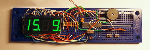
• Displaying time, day of week and date.
• Displaying time and date
• Displaying time only
• Set alarm clock - hours
• Set alarm clock - tens of minutes
• Set alarm clock - ones of minutes
• Alarm mode - off (0) / single (1) / work days (5) / every day (7)
Button "+" allows you to set alarm in alarm setting mode. In time / day / date mode
it sets the brightness of the LED display (1/32, 1/16, 1/8, 1/4, 1/2, full). The alarm indicator is lit when the alarm is enabled.
It blinks, when you are in alarm setting mode.
Setting:
Long press of "Mode" gets you into time and date setting. Then you can set:
hours, tens of minutes, minutes, tens of seconds, week day, day, month, year and enable/disable the automatic time.
You go trhough the steps using"Mode". Use "+" to set the value.
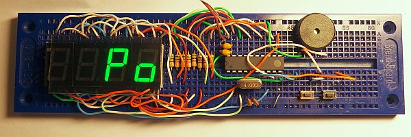
Automatic time setting (Au) allows you to enable or disable the automatic change to daylight saving time (DST) and back.
"Au1" = enabled, "Au0" = disabled.
The program for download:
source code in Assembler (ASM)
compiled in HEX file (2028 B)
How to write the program into the AVR is described here.