Introduction:
This device is good for switching on and off up to 16 independent appliances by remote control.
Pressing buttons 1 to 16 turns the corresponding output on, pressing it again turns it off.
The remote control operates on the infrared principle, with a range of up to 45m.
If 4 channels are enough for you, you can use
4-channel ON-OFF remote control.
Transfer Method:
Carrier frequency if the remote control is from 36 to 38 kHz.
Signals are transmitted by pulse distance coding, PDC. It has an advantage over pulse width coding (PWC) in
the lower power consumption of transmitter. Waveforms are shown in Figure 3.
Long gap (1726 CPU cycles) between pulses is log1, short gap (432 cycles) is log0.
Individual samples are separated by an ultralong space (6912 CPU cycles).
The pulse (burst) length is always 432 CPU cycles and is formed by a 16 impulses of carrier frequency.
The long start bit is omitted. The code consists of 4 data bits (sufficient to encode 16 buttons) and 4 check bits.
The check bits are logical inversion of data bits. They are used to verify the errorless transmission.
With inverted check bits the length of the sample is constant.
The difference between short and long gap and between a long and ultralong gap is always
4x, so that the transmission system is resistant to a wide divergences of clock speeds
of transmitter and receiver. It allows operation with the internal RC oscillators in both transmitter
and receiver, and it is not necessary to use crystals.
Button 1 code is 0000, button 2 code is 0001, button 3 code is 0010, ... button 16 code is 1111.
Transmitter (Remote controller):
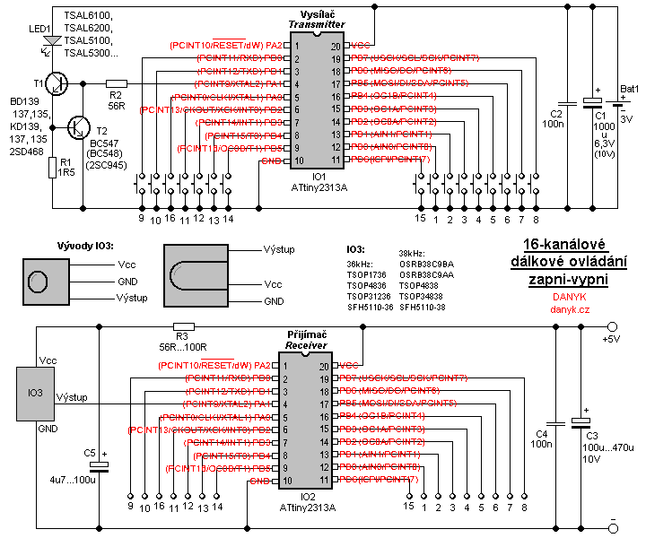
Remote control transmitter is controlled by the Atmel AVR microprocessor IO1 - ATTiny2313A running at 1 MHz frequency from internal RC oscillator.
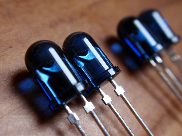
Commands are transmitted via infrared radiation emitted by the IR LED with a wavelength of 940nm. TSAL6100, TSAL6200,
TSAL5100 or TSAL5300 can be used. They are in 5 mm classical case, max. continuous current is 100mA.
When pressing a button, the transmitter sends the corresponding code. The program ensures that transmission
always ends up posting the entire sample regardless of when the button was released (transmission never ends during the sample).
It also ensures that every time you press button it sends at least 6 samples. Pulse current of the transmitting LED1 is set to about 320 to 400 mA.
The current is stabilized by circuit with T1, T2, R1, R2, so it does not decline significantly due to battery voltage decline.
The current is determined by resistor R1. Carrier frequency has 33,3% (1/3) duty cycle.
The total duty cycle of modulated signal is only about 6,6%, so a high pulse current can be used and obtain a reasonable range.
It is necessary to pay attention not to exceed the maximum current for the chosen IR LED.
Transmitting frequency is approximately 37 kHz (CPU frequency / 27).
The transmitter is powered from a 3V supply, eg. two AA or AAA cells, or other 3V battery. The minimal datasheet voltage of ATtiny2313A is 1.8V.
Consumption during transmission is about 20 to 30 mA. When no button pressed, IO1 enters Power Down mode and the transmitter
consumption is under 1uA (current much smaller than battery self-discharge, thus completely negligible). Situate C2 as close as possible to IO1.
Receiver:
The remote control receiver is controlled by IO2, also type ATTiny2313A, also clocked using 1 MHz from internal RC oscillator.
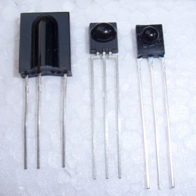
As the sensor of IR signal IO3 integrated infrared receiver is used. Receivers designed for frequencies from 36 to 38 kHz can be used
(the band-pass filter is relatively wide), eg TSOP1736, TSOP4836, TSOP31236, SFH5110-36, OSRB38C9BA, OSRB38C9AA, TSOP4838, TSOP34838 or SFH5110-38.
Integrated receiver receives, amplifies and demodulates infrared signal.
It has a built-in automatic gain control (AGC), suppression of ambient light, band-pass filter, demodulator and shaping circuit with TTL output.
All the above have a maximum sensitivity at 940-950 nm. Transmitting LED must correspond to this. Frequently occurring types od LEDs such as 850nm are unsuitable!
I found the OSRB38C9BA receiver to be the best. It has better sensitivity in comparison with tested and TSOP1736 SFH5110-38.
The receiver output is decoded in microcontroller IO2. When it receives the same sample 2 times and the check bits are consistent,
it toggles the corresponding output. After power is applied, the default state of all outputs is log0 (off).
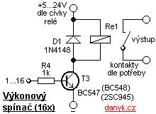
The outputs of the receiving circuit are connected power switches, such as relay according to Figure 2.
If you want to use all the channels, build the power switching circuit 16 times. Use the relay contacts dimensioned to the required voltage and current.
The relay coil may be 5V, then it can run from the same supply as the receiver. If the coils need higher voltages, such as 12V or 24V,
relay is powered from the the corresponding voltage supply. From a higher voltage, 5V can be obtained, eg, by using integrated circuit 7805 or 78L05.
When receiver has all outputs at log0 or unloaded, the power consumption is determined mostly by IO3. According to its type it is usually
about 0.5 - 5 mA. IO2 itself draws about 25uA when no output current. In the ON state the current consumption is determined mainly by the consumption of relay coils.
The relay coil should draw 500mA max., otherwise it is necessary to use another type of transistor for T3 and maybe different value of R4. You can also use N-MOSFETs.
Typical pinout of IO3 is shown in Figure 1, but for your specific type I recommend you to refer to the datasheet. Situate C4 as close as possible to IO2.
Range:
Range depends mainly on the type and current of the LED1 and type of IO3. Transmitting IR LEDs mainly differs in their total radiant flux (measured in mW),
radiance (measured in mW / sr) and transmission angle.
Also the maximum LED current is important. It should be also noted that the radiant flux and radiance of various LED datasheet can be measured at different currents!
The maximum range when well directioned is determined by the radiance. LEDs with the same radiant flux, but smaller angle, tend to have the greater radiance.
The LED with a small angle however is more critical to the direction of transmitter. At smaller distances, the signal is transmitted
even by reflections from objects and therefore it does not matter too much on its direction.
If the transmitter is not directed, the radiant flux is the most important for the range.
I chose as IR receiver OSRB38C9BA. As transmitting LED I tested four types and measured the range at the zero angle (tested with receiver OSRB38C9BA):
Highest range (45m) I reached with TSAL6100 and TSAL5100. Diodes TSAL6200 and TSAL5300 have about 30m range, but their direction is less critical.
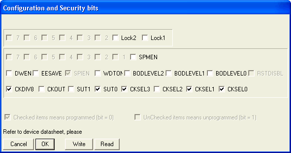
Note: The program is designed for ATTiny2313A. In old ATTiny2313 and ATTiny2313V it will probably not work as some of their pins don't have PCINT.
The program for free download:
Transmitter source code in assembler (ASM)
Receiver source code in assembler (ASM)
Compiled Transmitter HEX file (396 Bytes)
Compiled Receiver HEX file (422 Bytes)
How to write the program into the AVR is described here.