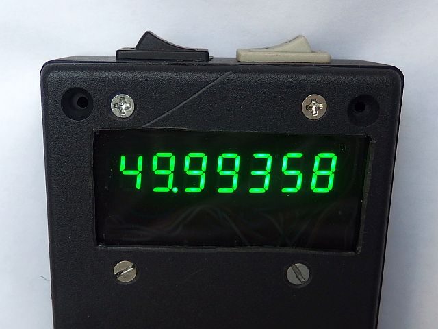
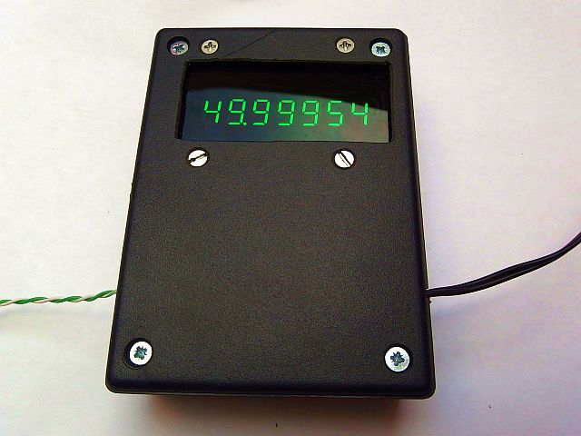
This frequency meter (counter) with AVR enables to measure the frequency from 0.45 Hz to 10 MHz and a period from 0.1 to 2.2 us in 7
automatically selected ranges. Data are displayed on the seven-digit LED display.
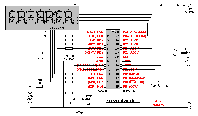
It is based on microprocessor IO1 - Atmel AVR ATmega88 / ATmega88A / ATmega88P / ATmega88PA, program for download you can find below.
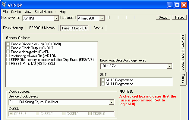
Setting of configuration bits is in Fig. 2. Principle of measurement is different than the previous
two frequency meters. Simple method of counting pulses for exactly 1 second, as
used in the previous two frequency meters (Frequency meter I.,
Frequency meter II.), does not allow measurement of the fractions of Hz. That's why I chose
another metroh for my frequency meter III. This method is much more complicated, but it allows to measure the frequency with a resolution of up to 0,000 001 Hz.
Frequency meter waits for the next rising edge, then starts to count pulses and also starts to measure the time.
After about 1 second (this time is not critical for accuracy) it will again wait for the next rising edge. With this edge it stops counting pulses and measuring time.
The frequency is then calculated by the equation f = number of pulses / measured time.
If the frequency meter is switched to the measurement of period (T), it is calculated by the formula T = measured time / number of pulses.
Then the cycle repeats again - frequency meter will again wait for the next rising edge, from which starts counting pulses and measure the time.
The measured signal enters inputs ICP1 and T0 to allow function of both Input Capture triggering (to
measure the time) and also to the input of external clock of timer/counter 0 (it allows counting pulses).
Overflow of 8-bit counter increments two 8-bit registers, so that a 24-bit information about the number of pulses is achieved.
Timer/Counter 1 (16-bit) also overflows into a pair of 8-bit registers, so that a 32- bit time information is available (1 LSB = 50ns).
When calculating the frequency, the 24-bit pulse counter value is multiplied by the 48-bit constant (2e13), resulting 72-bit number,
which is then divided by the 32-bit time stamp.
During the calculation of the period the 32-bit time value multiplied by the 16-bit constant (50 000), resulting 48-bit number, then it is
divided by the 24-bit pulse counter value.
The resulting value is in both cases transferred to 13-digit decimal (BCD) form and before the 6th digit, the decimal point is placed. The number is then shifted so that first
non-zero digit is at the beginning of the display. The frequency is always in Hz (Hertz), a period in us (microseconds). Automatic range selection changes the position of the decimal point,
eliminating the need for an indicator of metric prefixes (like Hz/kHz/MHz). The refresh rate is about 1 Hz (when measuring very small frequencies in the order of ones of Hz, refresh can be slower).
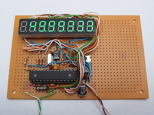
The cathodes of the display are connected to port D except PD4 and to PB4, the anodes to bits 0-5 of port C and to PB5.
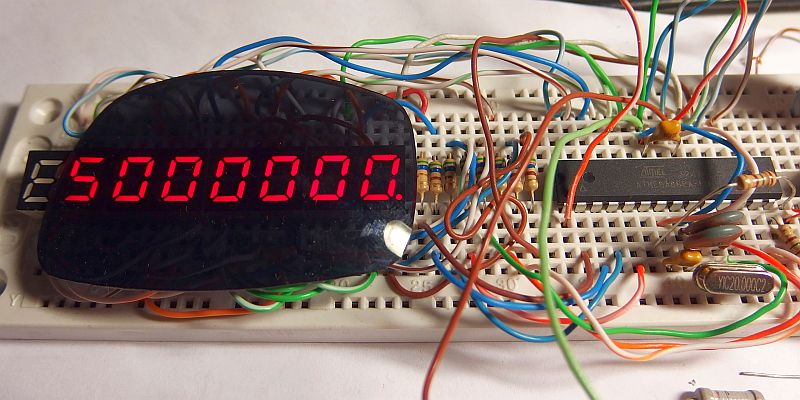
The seven-segment display unit can be assembled as four double digit LD-D028UR-C (red 7 mm), LD-D036UR-C (red 9 mm) or LD-D036UPG-C
(green 9 mm) with one digit unused. All the types mentioned have very high brightness.
Superbright display allows you to omit the usual transistors to amplify the anode current. The display is controlled multiplexi (matrix) way.
frequency of multiplexing is about 99.649 Hz. R1 to R8 determine the current onto display and thus its brightness. They are chosen so that the current does
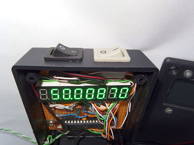
not exceed the maximum output pin current (40 mA). Switch S1 is used to switch between measurement of frequency f (open) and the measurement period T (closed).
Half period of the measured signal must be longer than the period of the crystal oscillator (limiting of the AVR architecture).
At 50 % duty cycle thus the frequencies up to 10 MHz can be measured. If the counter input is not connected to anything, it can display
meaningless values because the input impedance is high. You can prevent this by putting approx 100k resistor between the input and ground.
IO1 is clocked from 20MHz crystal (the maximum allowed CPU clock frequency). Accuracy depends essentially only on the crystal and capacitors C1 and C2.
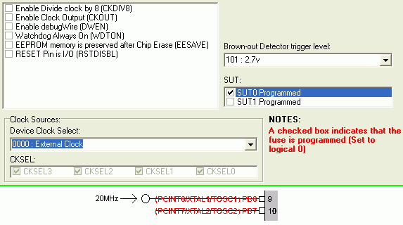
These capacitors can be replaced with tuning capacitance trimmers for precise adjustment. The circuit can also be modified for an external 20MHz clock source.
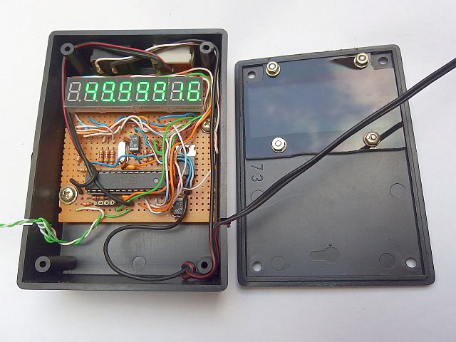
Change of wiring and setting of configuration bits you can see in Fig. 3. Frequency meter is powered from a supply of 4.5 to 5.5 V.
Current drawn at 5V is about 15-40 mA, depending on the number of shining segments (most current is consumed by the LED display).
Capacitor C3 should be placed as close as possible to AVR (IO1).
Ranges of frequency (f) meter:
Range 1 ... 0,450 000 Hz - 9,999 999 Hz, resolution: 0,000 001 Hz.
Range 2 ... 10,000 00 Hz - 99,999 99 Hz, resolution: 0,000 01 Hz.
Range 3 ... 100,000 0 Hz - 999,999 9 Hz, resolution: 0,000 1 Hz.
Range 4 ... 1 000,000 Hz - 9 999,999 Hz, resolution: 0,001 Hz.
Range 5 ... 10 000,00 Hz - 99 999,99 Hz, resolution: 0,01 Hz.
Range 6 ... 100 000,0 Hz - 999 999,9 Hz, resolution: 0,1 Hz.
Range 7 ... 1 000 000 Hz - 9 999 999 Hz, resolution: 1 Hz.
Ranges of period (T) meter:
Range 1 ... 0,100 000 - 9,999 999 us, resolution: 0,000 001 us.
Range 2 ... 10,000 00 - 99,999 99 us, resolution: 0,000 01 us.
Range 3 ... 100,000 0 - 999,999 9 us, resolution: 0,000 1 us.
Range 4 ... 1 000,000 - 9 999,999 us, resolution: 0,001 us.
Range 5 ... 10 000,00 - 99 999,99 us, resolution: 0,01 us.
Range 6 ... 100 000,0 - 999 999,9 us, resolution: 0,1 us.
Range 7 ... 1 000 000 - 2 200 000 us, resolution: 1 us.
The program for download:
source code in Assembler (ASM)
compiled in HEX file (2256 Bytes)
How to write the program into the AVR is described here.