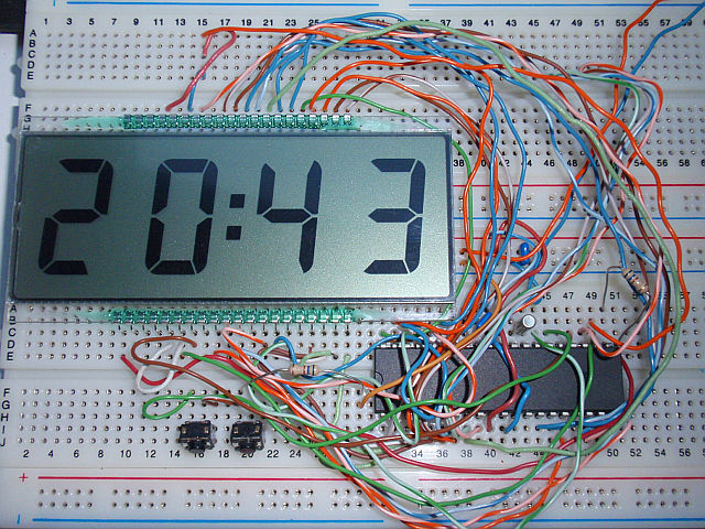
This is probably the simplest possible digital real time clock with LCD display and AVR. It displays time in the form hours:minutes.
It is set simply by using the "hours" and "minutes" buttons.
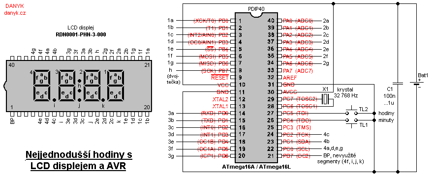
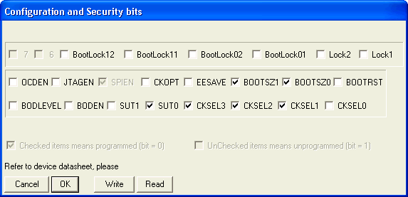
The clock is controlled by a microprocessor Atmel AVR ATmega16A or ATMEGA16L. The program for the AVR to download and configuration bits setting is available below.
The time is displayed on a four digit large LCD display with high contrast and character height of 25mm (1 inch), type RDN0001-PHN-3-000.
The display is controlled statica way (non-multiplexed). This requires a greater number of ports.
This is also the reason why 40-pin integrated circuit ATmega16A or L wach chosen.
LCD display drive frequency is 64Hz.
Clock is using the low-frequency watch crystal (32768 Hz) to achieve low power consumption.
This frequency enters the Timer/counter2 operating in asynchronous mode.
CPU is clocked from the internal RC oscillator set to 1MHz. When no interrupt occurs, the circuit enters the Power Save sleep mode.
Datasheet minimal voltage of ATmega16A / ATMEGA16L is 2.7 V.
According to my tests the clock begin working at 1.5 V and achieves satisfactory display contrast from about 2V.
The low power consumption (14uA at 2V, 20uA at 3V, 28uA at 4V) makes a battery the most suitable power supply.
The clock can be powered from two or three 1.5 V cells (AA, AAA, button cells) or 1.2V (NiMH, NiCd), one 3V button-cell,
Flat battery 4.5 V or Li-Ion or Li-Pol cell 3.6 V or 3.7 V. Using voltages above 5V is not recommended.
When using ordinary zinc-carbon AA batteries with a typical capacity of 1000mAh and consumption of clock about 20uA,
the expected battery life is over 5 years (excluding batteries self-discharge).
Place C1 close to IO1.
During first tests of the clock or in case of program adjustments, put a resistor in series with the battery (approx. 150 - 560R) in case of accidental short circuit
and also in series of buttons in case of accidental switching inputs to outputs. If you use the battery with a high short-circuit current,
connect series fuse or keep series resistor you connected during testing.
The program for free download:
source code in assembler (ASM)
compiled HEX file (398 Bytes)
How to write the program into the AVR is described here.