Introduction:
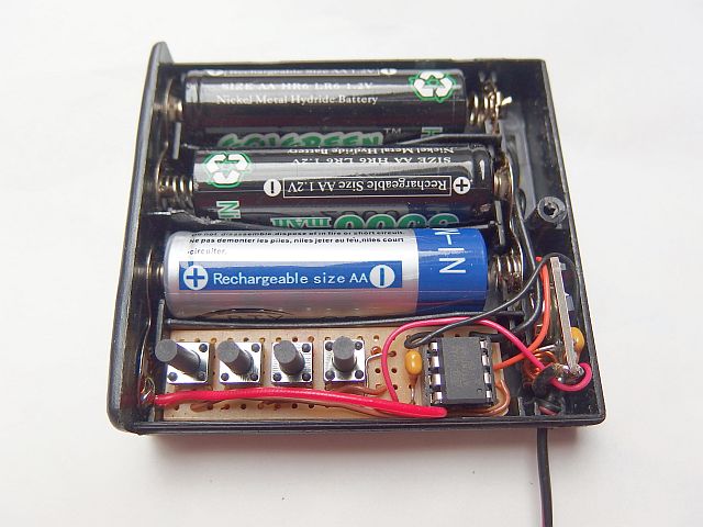
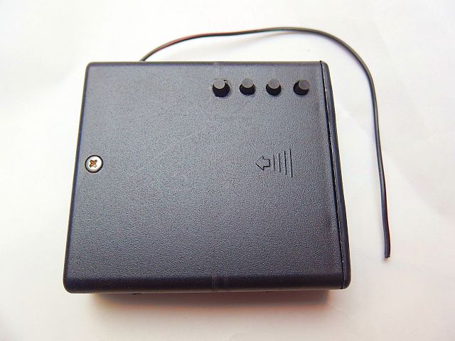
This device is used for radio remote controlling - turning ON and FF - up to 4 independent appliances.
Press switches 1, 2, 3 or 4 to turn it on, and press again to turn it off. The remote control operates on the principle of radio waves at a frequency of 433.92 MHz.
Unlike infrared remote control it is not necessary to aim the transmitter to the receiver,
it doesn't require line of sight between the transmitter and the receiver (can also be controlled through a wall, corner, ...) and allows greater range.
Transfer method:
The signal is transmitted from the remote control to the receiver via 433 MHz communication modules at 433.92 MHz.
This band can be used without a license for data transmissions with a small amount of data and transmitter power of up to 10mW.
With further modification, however, it can be used at
another band, for example 868 MHz, which allows up to 25mW. The transmitter can use ready-made communication modules - types that have 3 terminals:
power supply, ground, and input (transmitter) or output (receiver). Their use is very simple. Logic pulses at the transmitter input
appears at the output of the receiver (as long as it's within the range and no interference with other devices occurs).
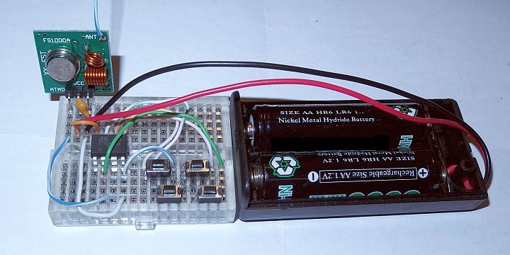
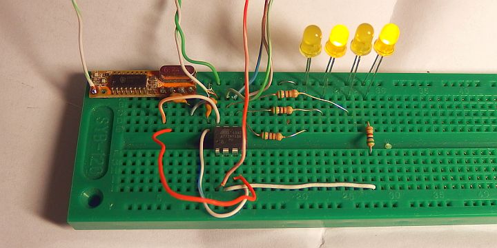
I chose the transmitter module FS1000A XD-FST and receiver module BX-RM12-433.
These modules have proven to me by wireless thermometer. Both antennas have a length of 17.3cm / 6.8inch (quarter wave).
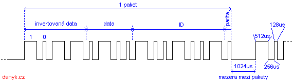
Data are transmitted by modulating the pulse length.
In one packet 16 bits of data are transmitted - the state of the buttons of transmitter (4 bits), the inverted state of the buttons transmitter
(4 bits) to check the accuracy of the transmission,
device ID (7 bits) and 1 parity bit for checking the correctness of the entire transmission.
A logic 1 is represented by 512us pulse lengths, logic 0 by a pulse 128us long, the gap between bits is always 256us,
the gap between packets is 1024us. The difference between short and
long pulse or between short and long gaps is always four times, which ensures resistance to large deviations of clock frequency of both
transmitter and receiver, so that crystals can be omitted. The average transfer rate is about 1.8 kbps. Seven-bit device ID is set
to 1001001 and can be modified in the source code if necessary (it must be set to the same value in both transmitter and receiver).
This is useful when you need independent operation of multiple pairs of devices. The ID can have 128 combinations.
Below you can download two versions of the program (one with ID 1001001 and one with ID 1001010), so you can build
two transmitter+receiver pairs that don't interfere with each other without having to modify the code yourself.
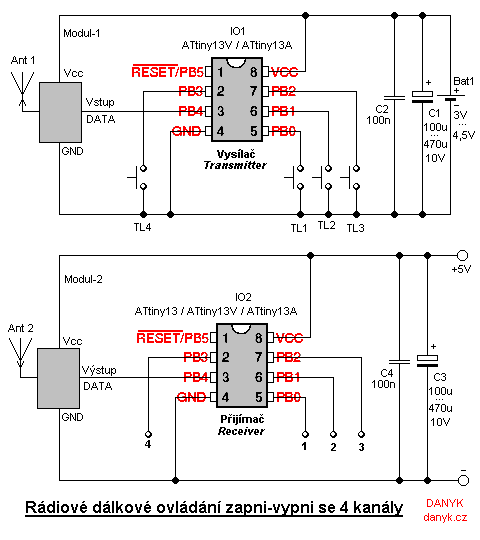
Transmitter:
The transmitter (remote controler) is controlled by a microprocessor IO1 - Atmel AVR ATTiny13A (ATTiny13V), running at a frequency of 1.2 MHz from
internal RC oscillator. Data are transmitted via radio frequency (RF) signal. Pressing the button sends the appropriate code.
The program ensures that each sample is sent at least 5 times, regardless of the time you press the button.
The transmitter is supplied by 3V or 4.5V, for example, two or three AA
or AAA batteries, depending on the supply voltage your transmitter module requires, or according to the required range.
When no button is pressed, IO1 enters power down mode and power consumption of the entire transmitter is under 1uA (current much smaller than battery
self-discharge, thus completely negligible). Capacitor C2 should be placed as close as possible to IO1. To the PB4 output you can connect a LED
via a resistor.
Receiver:
The remote control receiver is controlled by IO2, ATTiny13A (ATTiny13V, ATTiny13), also clocked at 1.2 MHz from the internal oscillator.
To receive the radio signal, Modul-2 (receiving RF module) is used. The output is evaluated by the microprocessor IO2.
It evaluates and processes the received signal and when it receives a code in
the correct shape - length of 16-bits, device ID is correct, parity bit and the inverse data are correct and a two consecutive packets are the same
- it evaluates the signal as errorless and the corresponding output flips.
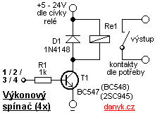
When power is applied, the default state of all outputs is log0 (off). The outputs of the receiver circuit connects the power switches, for example with relays,
as shown in Fig. 2.
If you want to use all the channels, build the power switching circuit 4 times. Use a relay with contacts rated for the desired voltage and current.
The relay coil may be at 5V, then it can be powered from the same supply as the receiver. If the coil requires higher voltage, for example 12V or 24V,
relay is powered from the respective voltage supply. 5V voltage from a higher voltage can be obtained, for example, using integrated circuit 7805 or 78L05.
Power consumption of receiver is, when all the outputs are in log0, or unloaded, determined mainly by RF Module. It is
about 2-6 mA. IO2 itself draws only about 25uA. In on state the consumption is determined mainly by consumption of relay coils.
The relay coil should draw less than 500mA, otherwise it is necessary to
use a different transistor typa as T1 and possibly lower R1 value (you can also use N-MOSFET). Capacitor C4 should be placed as close as possible to IO2.
Range:
RF communication modules and their range I discuss in more detail on the page about my
Wireless thermometer.
The program for download (ID is 1001001):
Transmitter source code in assembler (ASM)
Receiver source code in assembler (ASM)
Compiled Transmitter HEX file (168 Bytes)
Compiled Receiver HEX file (290 Bytes)
The program for download with a different ID (1001010) - for those who want a second pair (transmitter+receiver) that doesn't interfere with the first pair:
Transmitter source code in assembler (ASM)
Receiver source code in assembler (ASM)
Compiled Transmitter HEX file (168 Bytes)
Compiled Receiver HEX file (290 Bytes)
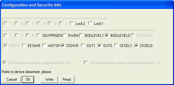
How to write the program into the AVR is described here.