This switching power supply has been created to power the digital camera.
Current onsumption of this camera is about 0.6 A and 1.3 A peak (flash charge).
For this purpose, it certainly could use a classic linear supply with eg LM317,
but the effectivity would be little over 30% with a heavy transformer and
stabilizer with a considerably heating heatsink. This switching power supply is a much more elegant solution.
On the Internet there are many schematics of switching power supplies with 3842,
auxiliary transistors or at least
countless unnecessary components. The diagram below shows a very simple
schematic of a small switching power supply with a single transistor and optocoupler.
Switching power supply without optocoupler with the indirect
stabilization would be even more simple, but its output voltage is not stable enough.
This switching power supply works as a flyback converter. The principle is simple:
After connecting the power the 1M 1W base resistor
partly opens the transistor. It induces the positive
voltage on the auxiliary winding (8 turns) and the transistor opens completely. When the capacitor 2n2 is discharged,
The transistor is turned off and the voltage induced to the secondary is
charging the filter electrolytic capacitor. When the 2n2 capacitor gets charged again, the transistor re-opens
and everything is repeated. When the desired voltage specified by resistive divider
3k3 and 10k opens the TL431 circuit, the LED in the optocoupler starts shining
and a phototransistor limits the current to the transistor base. This reduces the PWM duty cycle
and reduces energy delivered to the transformer. This method of stabilization
is very effective, the full load voltage drops by no more than 0.01 V.
This switching power supply can not work with no load, so the output loading
load resistor 33R is connected to eliminate this problem. Zener diode protects the powered device
before the overvoltage in case of failure of stabilization. Instead, you can use
another way of overvoltage protection, such as the one with SCR.
68n capacitor ensures EMI interference suppression, resistance 10R
reduces the inrush current when turned on. 2n2 capacity change can affect the operating frequency.
Printed circuit board must be arranged so that the primary (mains) and the secondary section were
apart far enough.
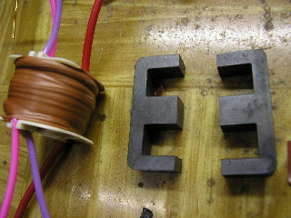
The transformer is wound on an EE ferrite core with an effective cross section
0.5 cm2. First, the first half of primary turns is wound, ie 40 turns.
The wire has a diameter of about 0.2 - 0.3 mm.
Then at least 8 layers of insulating tape are wound. Then the secondary coils.
For safety I used wire with thick insulation, which with only 4 turns is not a problem.
Then again followed by 8 layers of insulating tape. Furthermore, the auxiliary winding
8 turns is wound, using the same wire as the primary. Then again insulating layer,
which may not be as strong. Finally, other 40 turns of primary are wound.
Then again, a few layers of insulation. Between the core halves is placed one layer of
insulating tape to form an air gap to prevent core saturation.
Finally, the core of such sealed with glue.
This switching power supply can of course be modified for different output voltages, just
change the number of secondary turns (approximately 1 turn corresponds to 1V)
resistor 39R is changed by about 10R for each 1V and stabilized output voltage
be adjusted by changing the resistor 3k3 so that at the required voltage the
divider gives 2.5 V at input of TL431. Zener diode is chosen slightly
greater than the output voltage. Rectifier diode must have a reverse voltage
at least 8 times larger than the output voltage. For higher voltages, therefore, replace
Schottky diode by fast diode because the Schottky diodes
have always low rated reverse voltage. Of course, the output electrolyte must be rated for
the sufficient voltage.