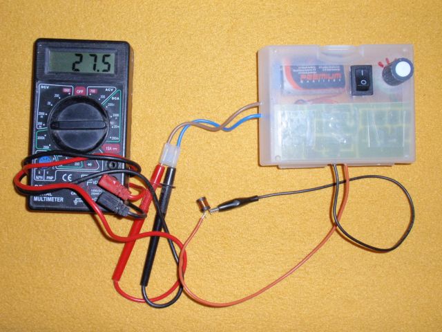
Introduction:
This meter can measure the inductance of the coils in a wide range of 10uH - 2H.
It acts as a complement to a digital voltmeter or a multimeter. Digital Multimeter is now possible to get below CZK 100,
but is the inductance-meter multimeters are rare.
Description:
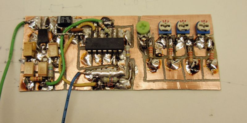
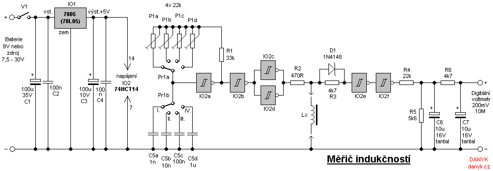
The basis of this simple meter is a sixfold 74HCT14 Schmitt trigger IC.
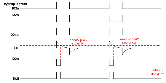
Inductance of the coil is derived from the time period for which the oscillator
keep the voltage on the coil above the specified limit (the lower threshold of Schmitt).
Range change is done simply by changing the frequency of oscillator.
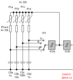
IO2a consists of an oscillator with a switchable frequencies. Switch to both C5a-d and P1a-d.
P1a to P1d trimmers are used to calibrate the ranges.
IO2b serves as an inverter, and IO2c and IO2d as a current amplifier.
These three inverters separate the oscillator from measuring circuit.
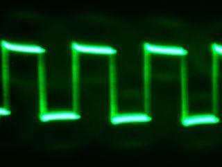
The duty cycle of oscillator is about 25%.
When the output of IO2c+d goes log. 1, the coil induces the full voltage
5V. This voltage then decreases exponentially and approaches zero. IO2e inverter senses the voltage. Output
is inverted, so the circuit IO2f has the correct the polarity. The output of IO2f stays
log. 1 from the moment when the oscillator flip to the log. 1, till the voltage across the coil drops below the lower Schmitt's threshold.
Pulse-width at IO2f output is proportional to the measured inductance coil. Output filter
R4, C6, R6, C7 converts the PWM to the DC voltage. It is then measured by a digital voltmeter (multimeter) set to 200mV range.
Supply voltage is stabilized by 7805 ir 78L05 to 5V, because it has a major impact on accuracy.
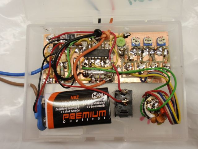
Capacitor C4 is to be placed as close as possible to IO2. Inductance meter's consumption is only about 4-8 mA and can be easily powered from 9V battery.
Improvements:
The circuit is inspired by the 74HC132 meters, which occurs in almost identical form in about ten different sites :) ... see literature.
This mindlessly copied circuit, however, suffer from poor accuracy and other problems. So I decided to make an improvement.
I have included the RD cell (D1 and R3), which allows recovery of the inductance. Without it, the inductance is
blocked by the protective diode on the input of the Schmitt (anode on the ground, the cathode to the input), and does not allow the inductor to recover between each
cycle. Residual current remains in the circuit on the next cycle and the measurement is greatly affected.
It turned out that
it is better to use the circuit of a series of HCT than HC. Its thresholds are located lower.
Oscillator duty cycle changes from 50% to 25%, which is more appropriate (Coil is not connecter to current too long and has more time to recover).
The lower threshold is also suitable for measuring small inductances. Lower threshold and lower duty cycle also eliminates the problem of original circuit:
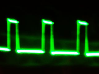
If too high inductance was connected, paradoxically, the meter showed zero instead of "1 _ _ _". This was caused by
that large inductance in the 50% duty cycle creates a nearly rectangular waveform with
peak at 2.5 V, which is not enough to flip the HC series inputs. With the HCT circuits, this problem does not occur.
The coils is connected to two inverters in parallel, which will increase the current abilities, reduce internal losses and thereby contribute to the accuracy.
HCT circuits and lower duty cycle also ensures less power consumption.
The diagrams in the literature mostly missing blocking capacitors
before and after 7805 (!!!). Here it is C1 to C4. I found that using the 200mV range provides much better accuracy
than 2V range, because the measurement range of 2V requires working with long pulses (up to 40%) and the RL circuit (R2 and LX) could not manage to stabilize before the next cycle.
In combination with the lack of D1 and R3, this may mean an error of up to tens of %. The divider R4, R5 circuit operates with duty cycle output pulses up to 20%.
I find that the zero trimmer (see literature) does not make sense, because the output voltage of schmitts in the log. 0 is negligible.
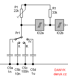
Initial involvement was only 1-2 ranges. I used 4 ranges, to measure the larger inductance. Higher ranges use
lower frequencies - hence the two-stage filter is used.
Callibration:
Each range is necessary to calibrate according to known inductance. This should preferably be a value of
50 - 90% of the scale, or display of the "1000" - "1800". Calibration of each scale is made by setting the
P1a - P1d trimmer so that the meter showed the correct value.
If you fail to
calibrate the meter, change the value of R1, the value of the P1a-d or C5a-d.
Individual ranges are listed in the table below.
If you do not measure the inductance of such a large range, some ranges may be omitted.
References:
pandatron.cz/?99&meric_civek
freecircuitdiagram.com/2009/05/12/inductance-meter-circuit
xtronic.org/circuit/digital-inductimeter-for-multimeter
electro2.webs.com/Inductance%20Meter.GIF
elektroarea.blogspot.com/2010/03/rangkaian-pengukur-induktansi.html
qsl.net/va3iul/Homebrew_RF_Circuit_Design_Ideas/Inductance_meter_using_DVM.gif
cqham.ru/projects/inductance_meter.jpg
geocities.ws/k7hkl_arv/K7HKL_Inductance_Meter.png
| Range | Max. value | Conversion | Operating frequency |
| I. | 2mH | 10uH/mV | 30kHz |
| II. | 20mH | 100uH/mV | 3kHz |
| III. | 200mH | 1mH/mV | 300Hz |
| IV. | 2H | 10mH/mV | 30Hz |