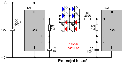
The figure below you can see the schematic diagram of a simple LED police flasher with two popular 555 integrated circuits. Both 555s work as astable flip-flop, each with a different frequency. Their outputs are connected to antiparallel two groups of LEDs. The circuit produces alternating series of strobes of LEDs of each group. The frequency and nature of flashing can be adjusted by changing the values of C2, C3, R2 and R3. R3 and C3 affect the flash rate, R2 and C2 affect the frequency of switching colors. You can also use a different number and different color of LEDs, but it is necessary to adjust the value of R1 not to exceed the maximum current of LEDs. The current also must not exceed max output current of circuit 555, which is 200mA. The circuit can be powered by any 12V (9 - 15V) supply.