Introduction:
This is a simple universal DC / DC converter (circuit, which converts DC voltage to another DC voltage).
The input voltage can be about 9 - 18 V and output voltage can be selected as needed in the range of about 3 - 50V.
The output voltage can be both lower or higher than the input. It is suitble for a wide range of purposes, such as powering equipment
(laptops, amplifiers, portable televisions, 5V USB appliances, 24V appliances ...)
from the onboard network of 12V car battery or solar cell, battery charging from solar cells, and so on.
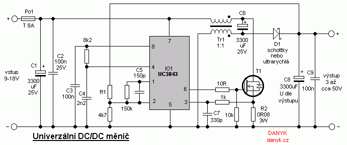
Circuit description:
The DC/DC inverter is built in the topology of integrated magnetics Cuk inverter (in my
article on converters
is a topology F). As a control circuit IO1 is used known UC3843 (click for datasheet in PDF).
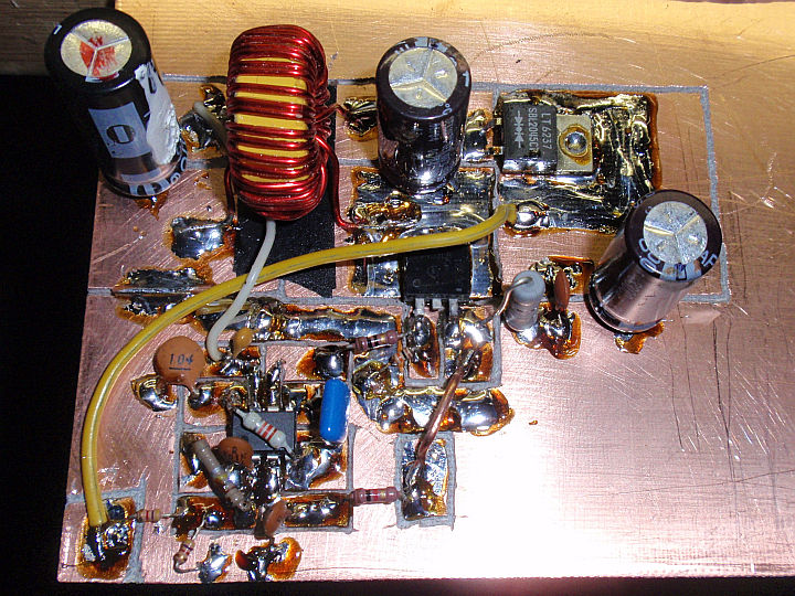
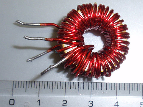
The inverter uses a transformer (if you want a double choke) Tr1. He must have a turn ratio of exactly 1:1. It is wound with two same wires simultaneously on
iron-powder (iron dust) toroidal core (ring).
Suitable is yellow-white core (material 26) or green-blue core (material 52). Both materials have a permeability of 75. Cores can be obtained eg from a PC supply
AT or ATX or from other SMPS or switching power converters.
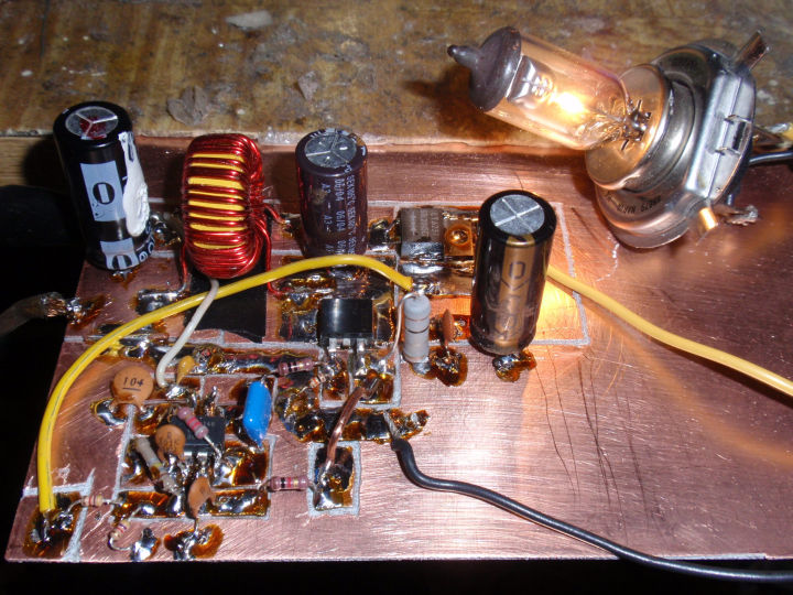
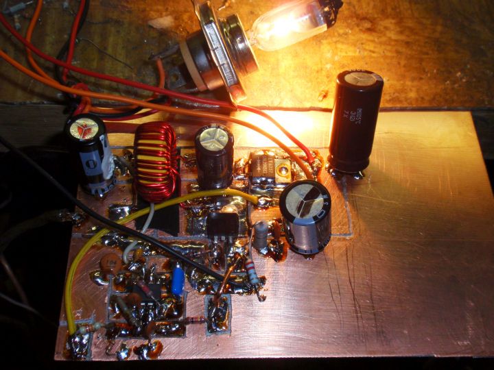
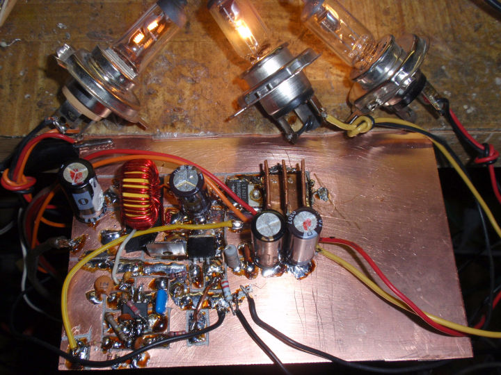
Wire diameter, number of turns and size of the core depends on the output voltage and power. The example of the trnasformer you can see at photos below.
The output voltage is determined by resistor R1. You can calculate the desired output voltage according to the formula:
R1 = (Uout - 2.5) . 1880
Voltage in Volts, the resistance comes in Ohms. Caution - Never switch on power without R1!
Voltage rating of C8 and C9 select according to the output voltage. Capacity of C1, C2, C6, C8 and C9 can be adjusted depending on the desired output of inverter.
C1, C6 and C8 should be low ESR type. T1 is a low-voltage N-type MOSFET with the as low as posible resistance in the closed state.
T1 and D1 during operation sees the sum of the input and output voltage and must be rated at least 1.25 times the maximum intended voltage.
The working frequency is about 90-95kHz. The inverter is suitable for power of several watts to tens of watts.
The required parameters should be adapted to power components (D1, T1, Tr1 and electrolytes). For higher power also place
T1 and D1 on heatsink. R2 determines the threshold of current limiting. If this threshold is chosen appropriately to used power components
and cooling, the DC/DC converter is resistant to overload and short circuit.