In previous article about the Atmel AVR We have only blinked with LEDs, without influence of events outside the microprocessor. All ports operated only as outputs, there was no input. Now we will show how to connect control buttons to the microcontroller and how to the INTO and INT1 pins as inputs. To demonstrate this, I chose the Atmega8 (You can also use the newer Atmega8A). The buttons are connected to pins 4 and 5, which are bits 3 and 4 of the port D, but also have an alternative function - INT0 and INT1. These alternative functions are in our interest. They are external interrupt sources. If these interrupts are enabled, you can use these inputs to trigger the interrupt handler. INT1 interrupt is enabled using the most significant bit in register GICR. Interrupt INT0 is enabled using the second highest bit. Enabling both interrupts we do by setting the two upper bits of GICR to 1:
LDI REG,0b11000000
OUT GICR,REG
Next, we have to select what will trigger the interrupt - the interrupt sensitivity. This is done by using the MCUCR registr. Sensitivity of INT0 is chosen by combination of two bits - ISC01 and ISC00. Sensitivity INT1 is chosen bits ISC10 and ISC11. In our example, we want sensitivity to the falling edge, and therefore each pair is set to 1 0. We can do it this way:
LDI REG,0b00001010
OUT MCUCR,REG
The position of bits in registers GICR and MCUCR shows table:
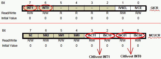
The meaning of pairs of bits ISC01 and ISC00 or ISC10 and ISC11 in registry MCUCR setting the sensitivity of inputs:
0 0 ... logic 0 triggers the interrupt
0 1 ... any logical change triggers the interrupt
1 0 ... falling edge triggers the interrupt
1 1 ... rising edge triggers the interrupt
Pressing the button now initiates the appropriate interrupt handler. In our example, this is the increment / decrement the working register
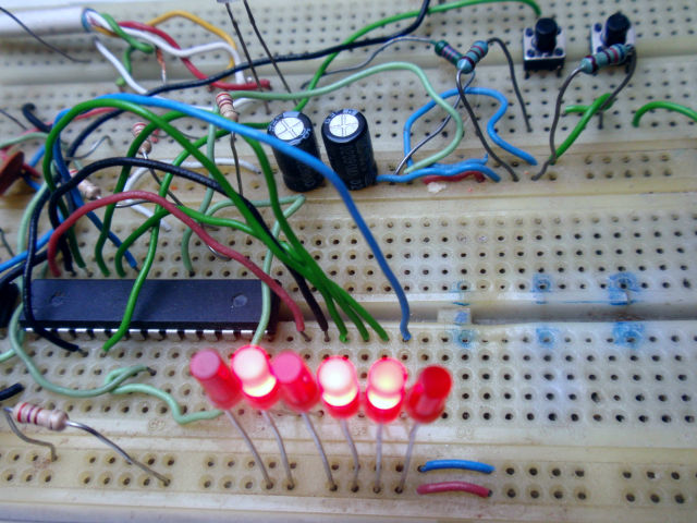
REG and subsequently sending its state on output, which is a port C - its first 6 bits. Its status is indicated by 6 LED.
Now you have built the binary counter, you can press a one button to add 1 and second button to substract 1.
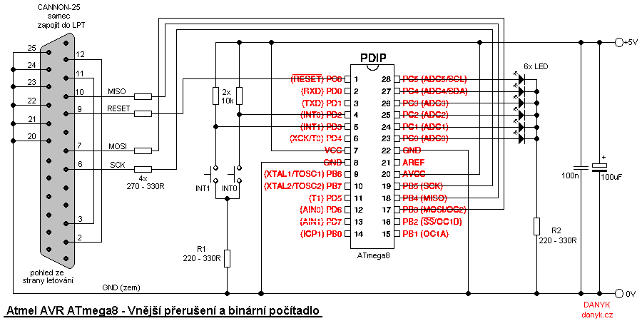
Schematic diagram of this experimental circuit you can see below. This video on the bottom of this page demonstrates the function.
You can certainly find a lot of other things to which buttons can be used :).
When no interrupt is being executed, the program loops it the endless loop (called SMYCKA in the cource code).
There's nothing in the loop, but you can add something.
The program is available for download below.
The entire program for download:
Binary counter with interrupts - source code in assembly (ASM)
Binary counter with interrupts - compiled HEX file