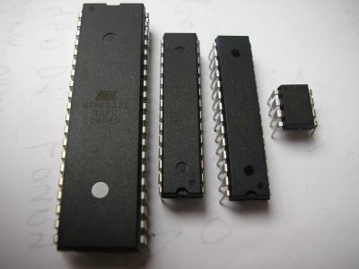
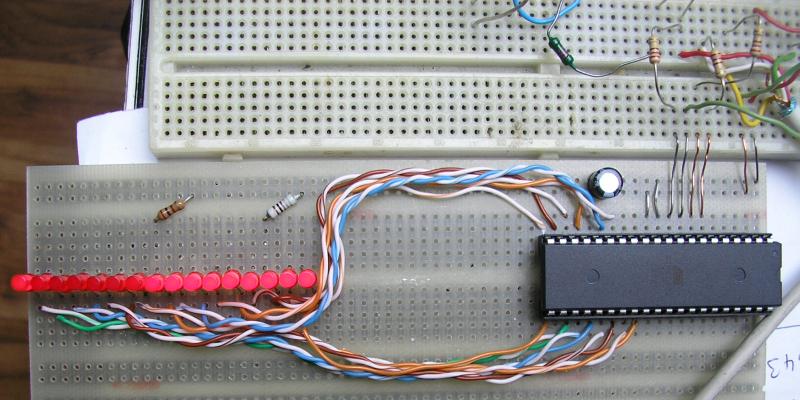
Recently I started programming Atmel AVR microcontrollers. I bought a few pieces of ATmega and ATtiny.
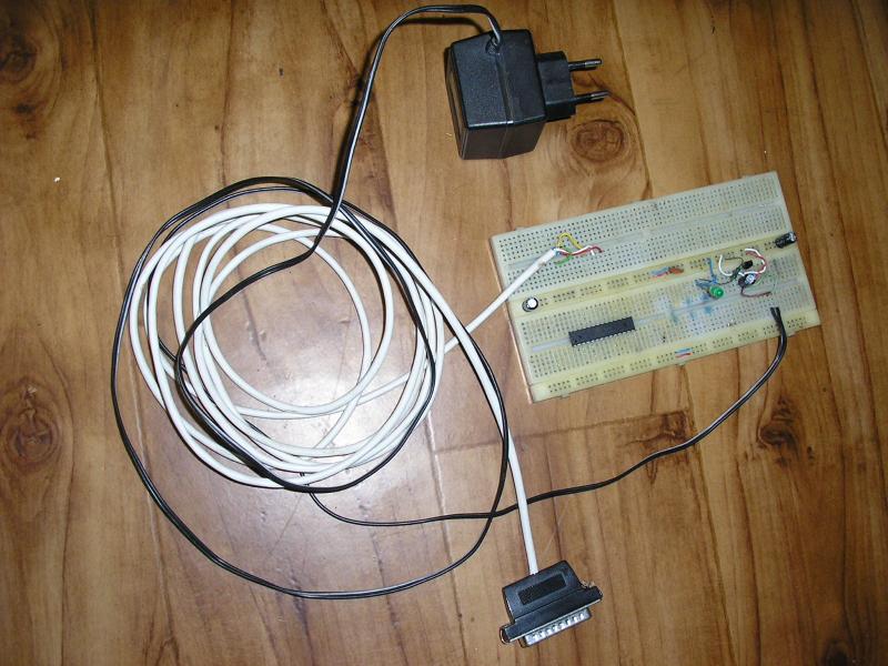
I created a simple programmer connected via LPT. It is essentially a connector cable, a few resistors
and 5V supply (with 7805 of course). As a development and simulation environment I am using AVR Studio downloaded from Atmel and for programming I am using PonyProg.
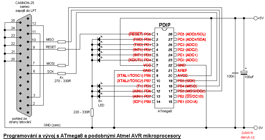
Programming is done by connecting signals MISO, MOSI, SCK and RESET to corresponding pins on the microprocessor and also connecting power supply.
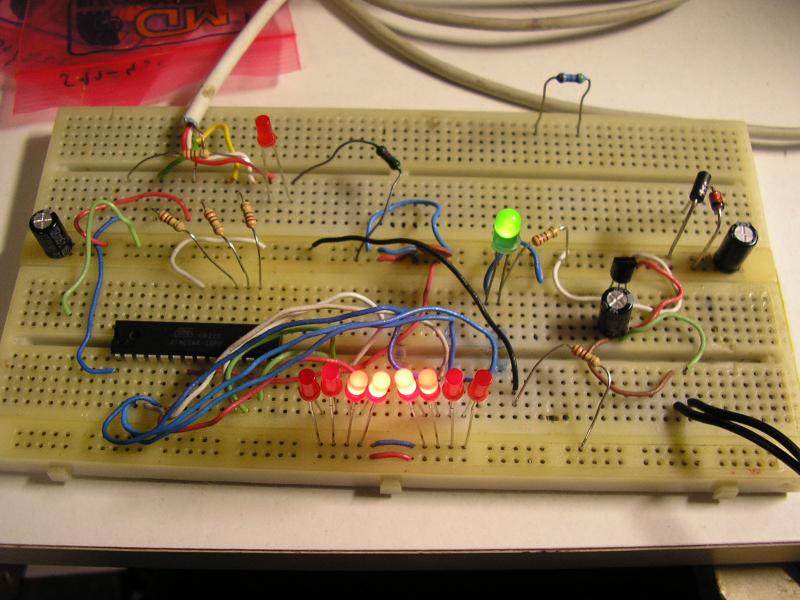
The first experiments led to light snakes with ATmega8, the AVR with 28 pins and 8kB of memory. I use port D, which
has all 8 pins and stays free even during the development.
Port C is lacking a bit PC7 and PC6 is used as RESET, so it has only 6 free pins.
Port B is used to program and for a crystal for precise timing, so only 3 pins remain free.
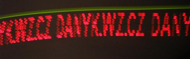
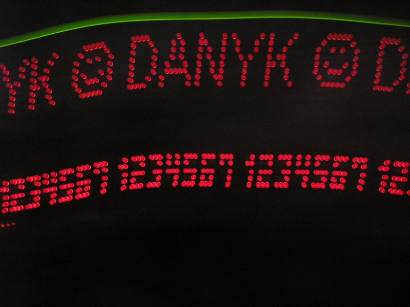
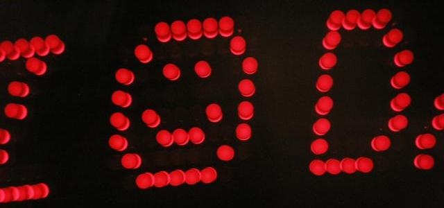
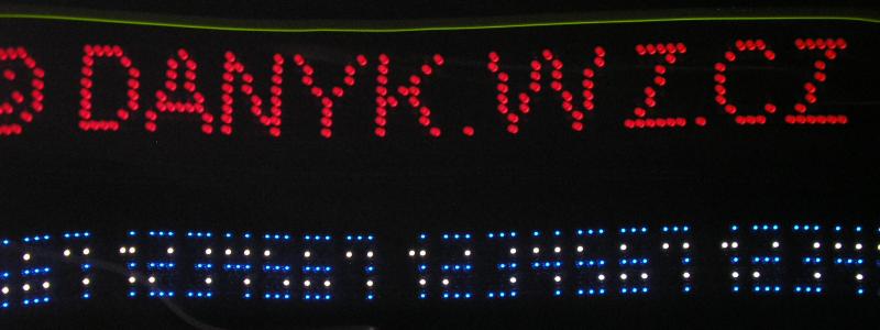
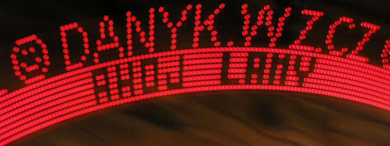
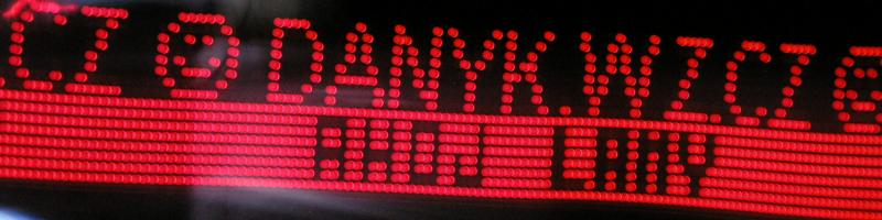
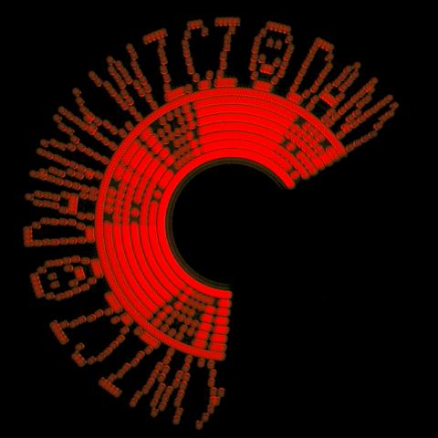
After experiments with light snakes I came to the air light display. It is a matrix display
with mechanical scanning, bar of LEDs renders text or pictures in the air due to the human eye's or or camera's persistence of vision.
First I tried the parallel scanning, in which all LEDs can be lit simultaneously, but it did not work well. Therefore
I moved the serial scanning, characteristic in that always no more than one LED at the same time is lit and thus
display is sharp (not create horizontal lines, but points). Another advantage is the use of a single resistor for all LEDs.
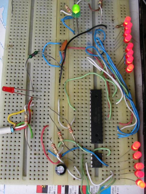
Programming and development schematic with ATmega8 AVR and similar you can see in the diagram below.
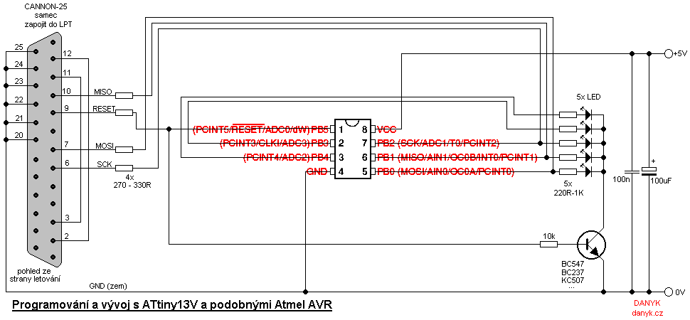
I also tested snakes and aerial display with a small 8-pin ATtiny13, which has 1kB memory and only usable 5 pins (port B).
The outputs are shared with programming pins and hence it is necessary to disconnect the LEDs during programming.
First i did it manually, but then I found automatic way to do this:
the RESET will to log 0 during programming and so NPN transistor closes and disconnectd the LEDs. Otherwise, everything is pretty much the same
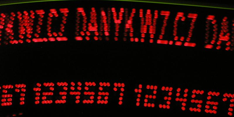
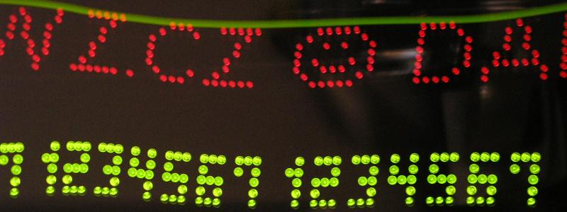
As with other AVR. This circuit I could use to display numbers using 5 LEDs in different colors. Even this
display uses a serial scanning, in which only one LED lights at one time.
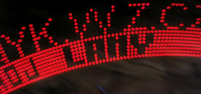
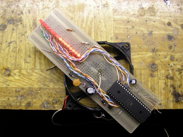
Finally, I went to the circuit ATmega32. This is a big 40 pin microprocessor with all four 8-pins ports and memory 32kB.
Only port B is used as the programming port. RESET input separate, not shared with other function. This circuit
I used for air display with 16 LEDs on ports C and D. It was necessary to turn off the setting bit JTAGEN that associated pins
PC2...5 with alternative functions. In this circuit, I used a double serial scanning. On each of the two ports is always lit one LED at most.
Every 8 LED has a common resistor. In addition to manual scan (circuit waving in the air), I tried to attach the circuit board to the motor and spin it
to form a propeller display. I used the motor from an 8cm PC fan and mechanical transmission of power. For this motor it was a big load and it spun quite slowly.
Next time I plan to use a more powerful motor and inductive voltage transmission using coils. ATmega32 programmer circuit is similar to that
of ATmega8, but there are a more unused pins. The pinout can be found in the datasheet.
Software: AVR Studio development environment you can download here.
To write the program into the microprocessor you need PonyProg that you can download here.
In PonyProg you need to set the correct type of microprocessor (top) and in settings select parallel port LPT1.
If you are experiencing problems with access to LPT with PonyProg, UserPort will help you.
How to write the program into AVR using PonyProg I describe here.
Below are some of my simple programs to download in ASM. Note for professionals: they are written dirty way :).