Introduction:
This is probably the simplest possible digital oscilloscope.
It allows both a single measurement and real-time measurement and external and internal triggering.
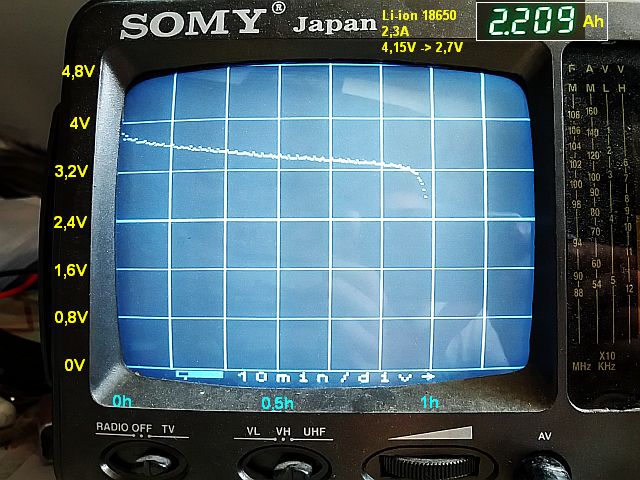
This scope is suitable for measuring everything from very slow phenomena (up to 8 days) to the frequency in the tens of kHz.
The oscilloscope is equipped with a PAL TV output (composite video). To view it, use any TV with Composite video input (CRT, LCD, ...).
Schematic:
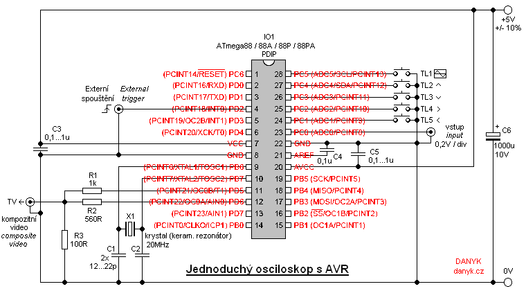
On Fig. 1 you can see the schematic of this simple scope.
The main component of the digital oscilloscope is integrated circuit IO1 - Atmel AVR microcontroller ATmega88, ATmega88A, ATmega88P or ATmega88PA.
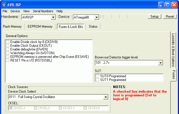
Its program is free to download below. The picture below is also shows the setting of the configuration bits. IO1 circuit is clocked at its maximum frequency of 20 MHz,
obtained from an external oscillator with a crystal or ceramic resonator. For the sampling, it uses the internal analog-to-digital converter (ADC).
The measured signal enters the ADC0 input (pin 23). As input for external trigger PCINT18 (pin 4) is used.
Keyboard consisting of 5 buttons is connected to the ports PC1 to PC5. The circuit uses an internal voltage reference, so the AREF pin is connected
only to a decoupling capacitor C4. PAL output signal is generated using a simple 2-bit digital-to-analog (DA) converter
made up of R1, R2 and R3 connected to PD5 and PD6. The converter generates four voltage levels, corresponding to the level of synchronization, black, gray and white.
In case of wrong signal level, it can be adjusted using R3 or R1 and R2. However, it is necessary to maintain approximately the relation R1 = 2x R2.
Video frame rate is 50Hz and line frequency is 15.625 kHz. White level corresponds to the voltage around 1V.
Capacitor C3 should be placed as close as possible to pins 7 and 8 and C5 as close as possible to pins 20 and 22.
The circuit is powered from a power supply of 5V +/- 10%.
Parameters:
The time base is in the range of 50us - 6h / div chosen in steps. Measurement time is up to 8 days.
Total 960 samples are scanned. Screen resolution with frame and OSD: 242 x 264, resolution of measurement window:
240 x 256, measuring area resolution: 960 x 256 (measuring area can be scrolled).
Sensitivity is 0.2 V / div. A resistive divider can obtain additional levels of vertical sensitivity.
Control:
Use the up and down buttons to set the time base in steps from 50us/div to 6h/div.
Use the left and right to scroll the measuring area.
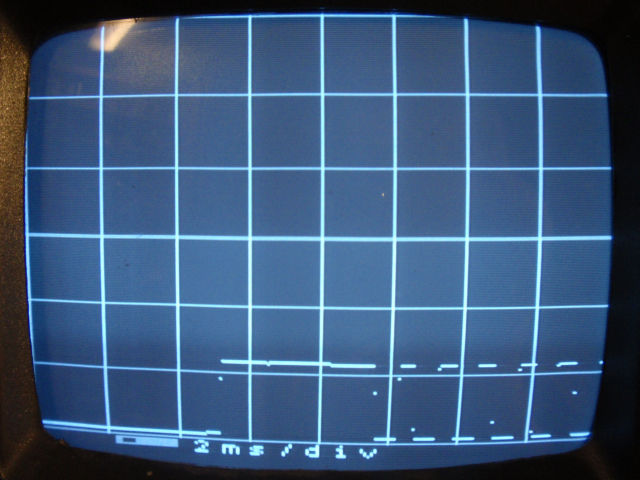
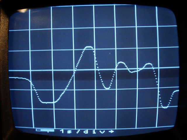
At the bottom of the screen theres the OSD display. It contains a slider showing the actual scroll position. Next to it, the time base is displayed.
Pressing TL1 starts single measurement. Ongoing measurement is indicated by an arrow on the OSD. After the one-time measurement the
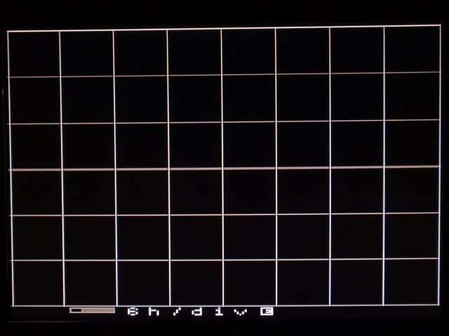
arrow disappears. If you connect the external trigger input, the circuit waits for the leading edge of the external trigger input after pressing TL1.
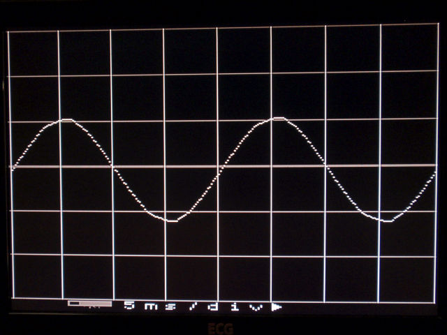
While waiting the symbol "E" (external trigger) appears on the OSD. Rising edge starts the measurement. Hold down TL1 longer than 1 second to start measuring in real time.
This is indicated by a triangle (Play symbol) on the OSD. In real-time mode, the trace on the screen is constantly refreshed. Real-time mode
can be stopped by briefly pressing TL1. During the measurement, the slider also shows the measurement position indicator
(When a short time base is set, it may not be visible, as well as an arrow indicating the one-time measurement).
Long press of the up, down, left and right allows quick transfer between different time bases and fast scrolling.
The program for free download:
Source code in assembler (ASM)
Compiled HEX file (4 606 Bytes)