BM366 inductance and capacitance meter was manufactured by Czechoslovak Tesla national enterprise based in Brno from the late 1950s to the 1970s.
Thanks to its small dimensions and low weight, it is suitable for workshop and repair practice, as well as for laboratory measurements.
The device works on a resonance principle. The measured inductance or capacitance forms together with the built-in capacitance or inductance an
oscillating circuit to which a high frequency voltage of variable frequency is applied. When tuning the oscillator to a frequency that corresponds to the
resonant frequency of the oscillating circuit, the analog meter will show the greatest reading. The tuning capacitor has a calibrated scale
in the values of capacitances and inductances.
The switch is used to select whether we measure inductance (Lx) or capacitance (Cx). The measured inductance is connected between terminals Lx and ground, capacitance
between terminals Cx and ground (directly or via leads). The capacitance of the leads can be compensated by the Co trimmer, located in the left side wall.
Set the range switch to the range corresponding to the expected value of the measured component. Use the knob to tune the oscillator.
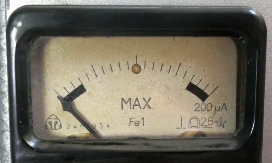
When finally tuning the oscillator to resonance, the zero of the indicator needs to be in the middle of the scale around the red dot marked "max".
For this, you need to set the sensitivity appropriately. The sensitivity potentiometer is has a built in mains switch.
On the front panel there is a light indicating power on (6V 50mA telephone bulb).
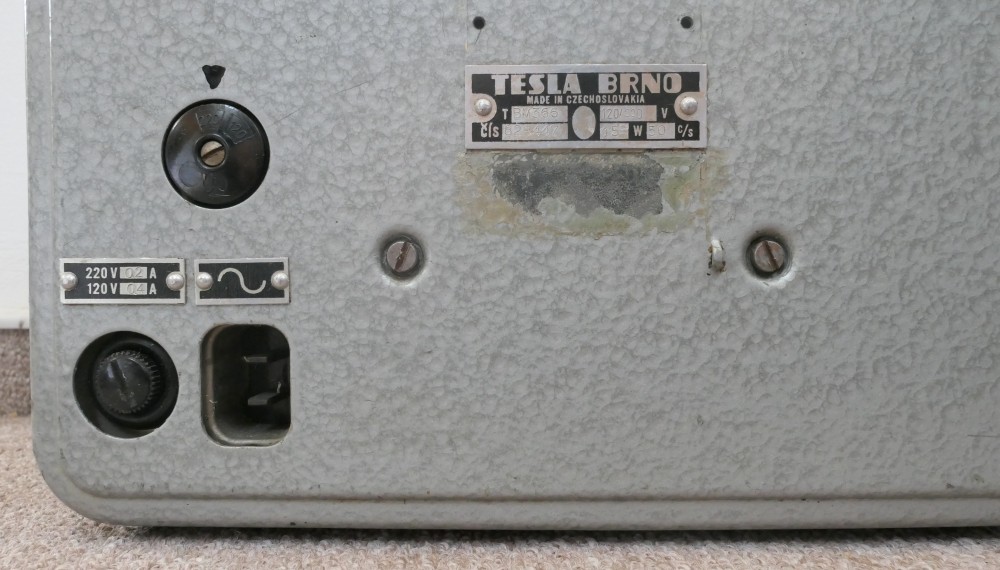
This device is powered from an AC mains 120V/220V 50Hz (the voltage selector is on the back).
The indicated power consumption of the device is 15W, the weight is about 5.2kg and the dimensions are 260 x 190 x 145 mm.
The device is equipped with tubes:
1x 6F32 steep hf pentode
1x 6CC31 double triode
1x 6Z31 two-way rectifier
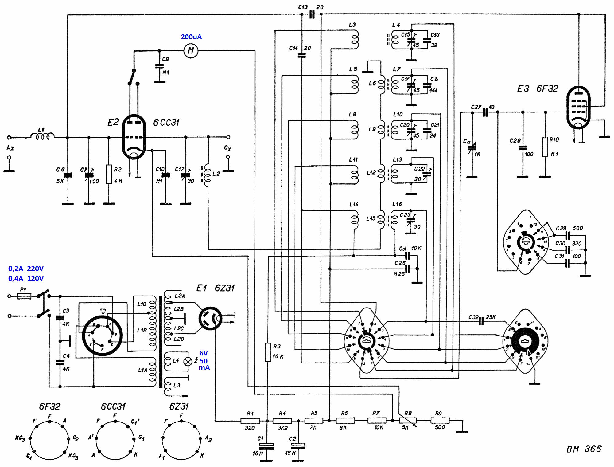
Tesla BM366 inductance and capacitance meter - schematic I (older version, R10 values, no resistor parallel to L15).
Tesla BM366 inductance and capacitance meter - schematic II (newer version, E24 values, a parallel resistor added to L15).
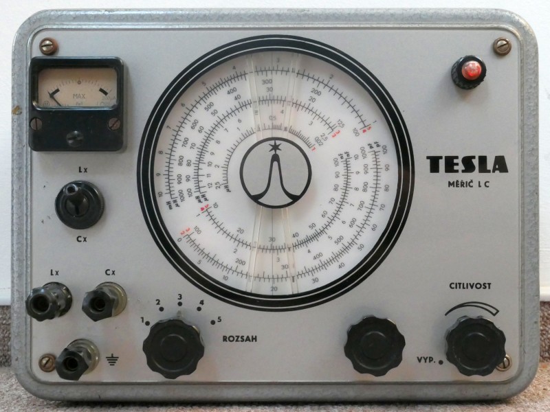
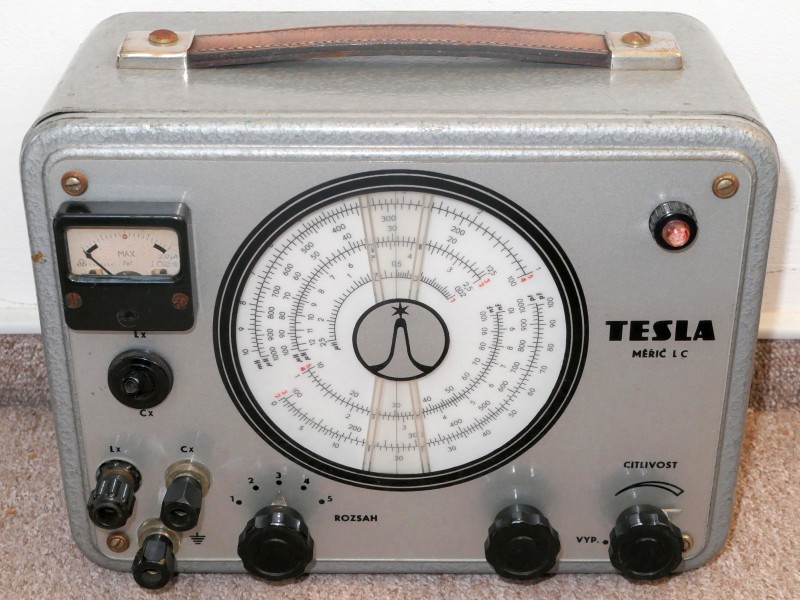
Tesla BM366 inductance and capacitance meter in operation after restoration - measuring a capacitor.
Tesla BM366 inductance and capacitance meter in operation after restoration - measuring an inductor. The next photos are before and during the restoration.
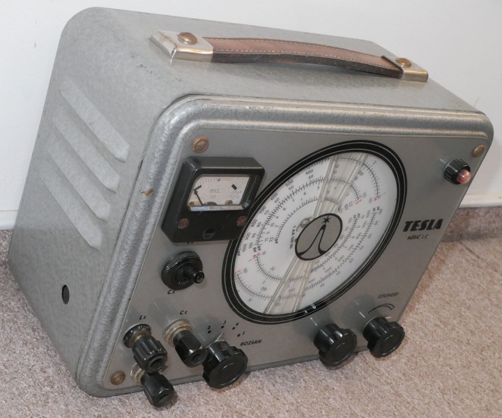
Tesla BM366 inductance and capacitance meter - front panel (version with labels in Czech, there was also a version in English and possibly Russian).
Tesla BM366 inductance and capacitance meter. Somebody replaced one terminal with a different one.
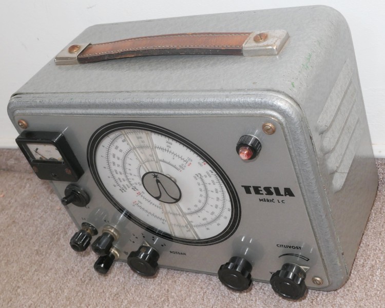
Tesla BM366 inductance and capacitance meter from the right side.
Tesla BM366 inductance and capacitance meter from the left side.
Tesla BM366 inductance and capacitance meter - analog meter.
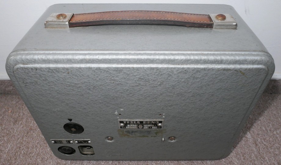
Tesla BM366 inductance and capacitance meter from the back.
Tesla BM366 inductance and capacity meter, rear detail - mains voltage selector, fuse and mains input.
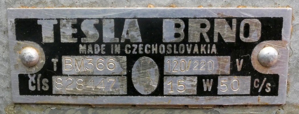
The label of BM366.
Tesla BM366 bottom.
Tesla BM366 inductance and capacitance meter uncovered.
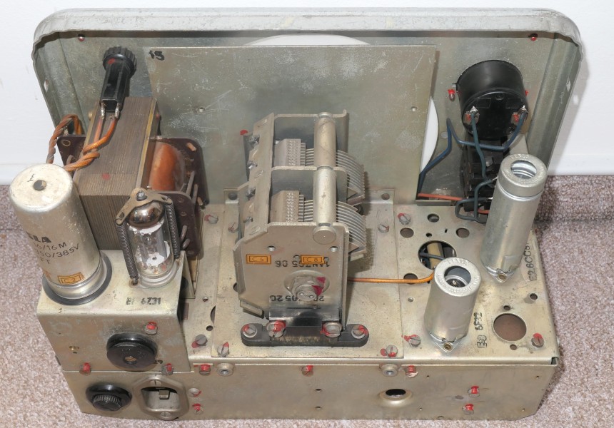
Tesla BM366 - chassis after removing tube covers. On the left you can see the power supply - mains transformer, 6Z31 rectifier tube and the smoothing capacitor (16 + 16 uF).
In the middle is the tuning capacitor. On the right there are 6F32 and 6CC31 tubes, the analog meter, C9+10 and the L / C switch.
Tesla BM366 - chassis seen from the power supply side.
Tesla BM366 - chassis seen from the tube and meter side.
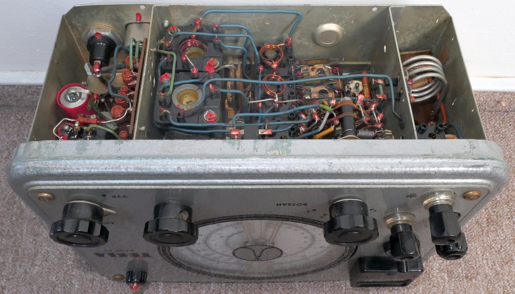
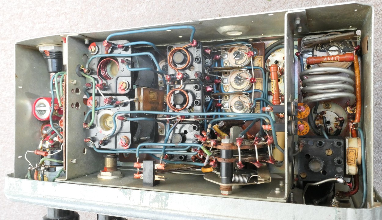
Tesla BM366 - chassis from below.
Tesla BM366 - chassis detail from below.
Tesla BM366 - chassis from below - detail of the area near the measuring terminal.
Tesla BM366 - chassis from below - detail of the area near the fuse, mains voltage input, potentiometer with a switch, interference suppression capacitors, C26 and dropping resistors.
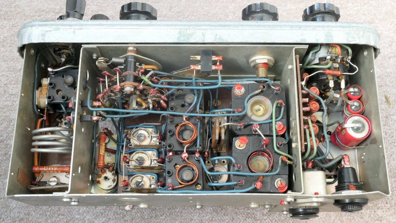
Tesla BM366 - chassis from below. In the middle part you can see the range switch and tuned circuits - coils and capacitors for individual ranges.
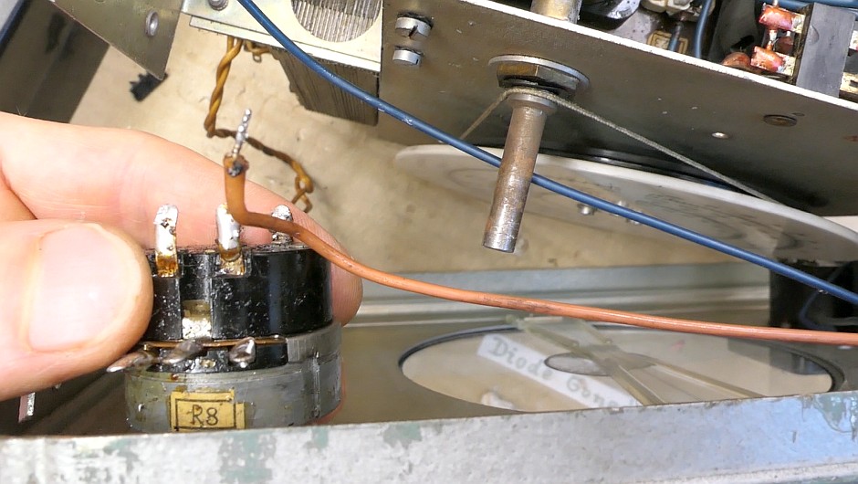
Unfolded front panel, before replacing the sensitivity potentiometer
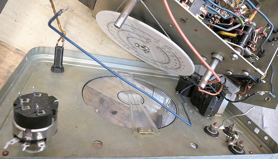
Unfolded front panel, after replacing the sensitivity potentiometer. On that occasion, I also changed the terminals so that all 3 were the same.