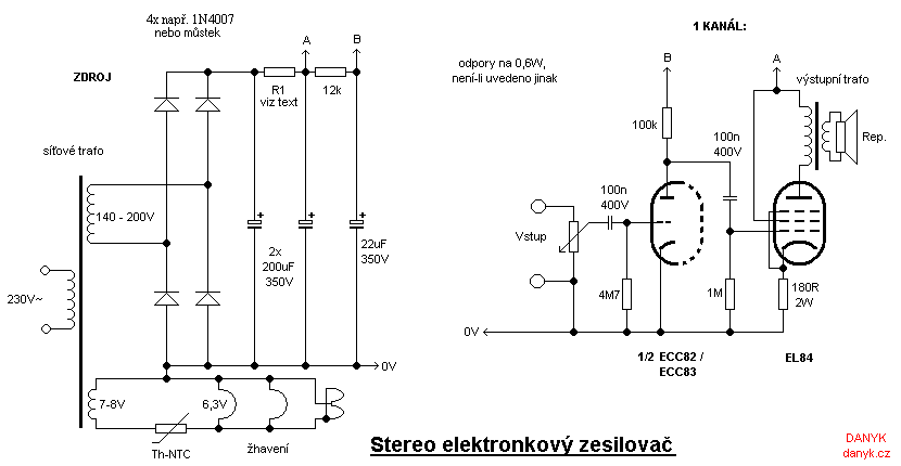
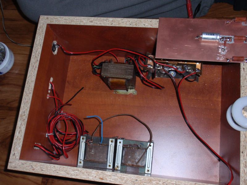
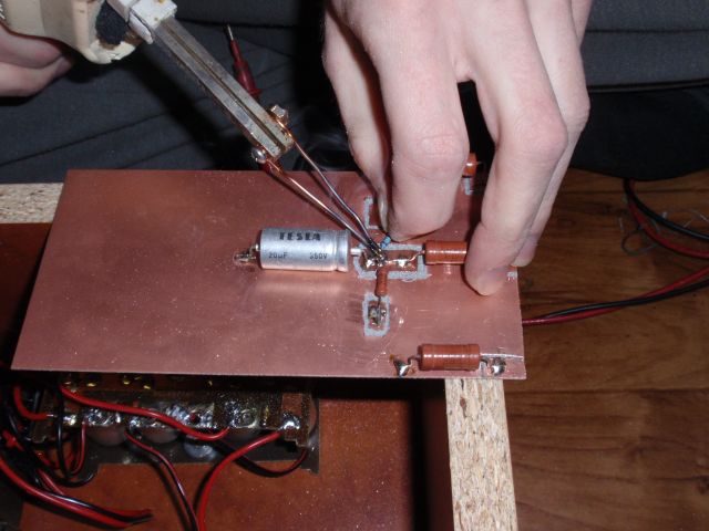
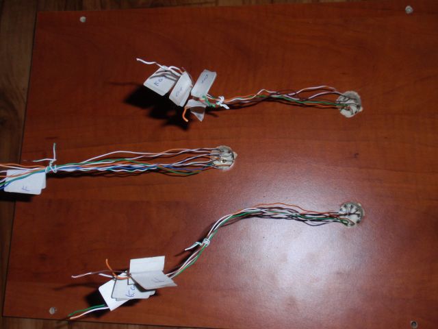
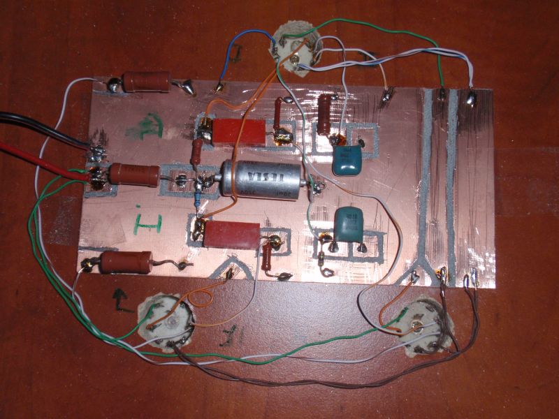
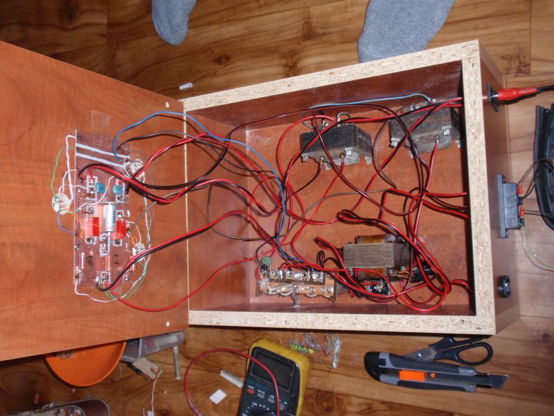
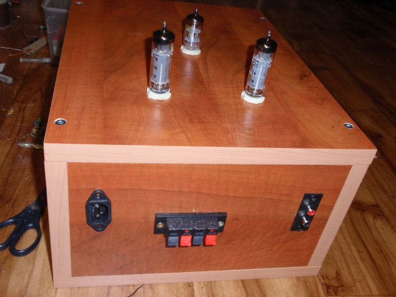
I bring another vacuum tube amp, this time with tubes ECC82 and 2x EL84 or similar. It is in my favorite class A. The sinusoidal power output (no PMPO) is about 2x 5W. The principle of the amplifier is I think obvious from the diagram. The power supply is using the C-R-C filter. The anode voltage for the triode (output B) has additional filtration with the 22uF capacitor for excellent mains ripple suppression. R1 is chosen so as to achieve a suitable anode voltage. Selects usually 190 - 250V. If you do not need the maximum power, you may use even lower voltage. Too small value of resistor R1 may cause ripple and hum. For clarity, the diagram is drawn for only one channel. For stereo amplifier is of course built 2x. Heaters of the tubes are connected in series with NTC thermistor for inrush reduction - this prolongs the tubes life. The volume potentiometer is the double logarithmic (stereo), the value is not critical. In the event that the amplifier is oscillating, connect approx 1k resistor in parallel to the inputs. If the amplifier will continue to oscillate, connect the capacitors of around 47pF between the anode of each triode and the corresponding pentode. Oscillations can also be causes by bad wiring (input and output cables are close together). The output transformers are airgap (non-interlaced core). Impedance transformation ratio is the square of the voltage ratio (the ratio of the number of turns). It should be selected according to the output impedance of tubes and the impedance of speakers.
