Push-pull inverter with BUP213 IGBT
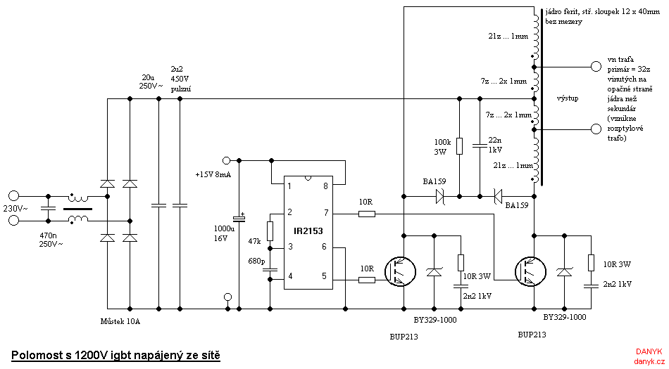
This circuit was created in an attempt to create an inverter without floating gate drive. It should use 1200V IGBT (600V ones are not enough)
and the output transformer, the advantage is
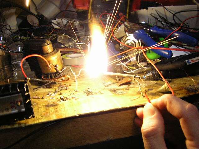
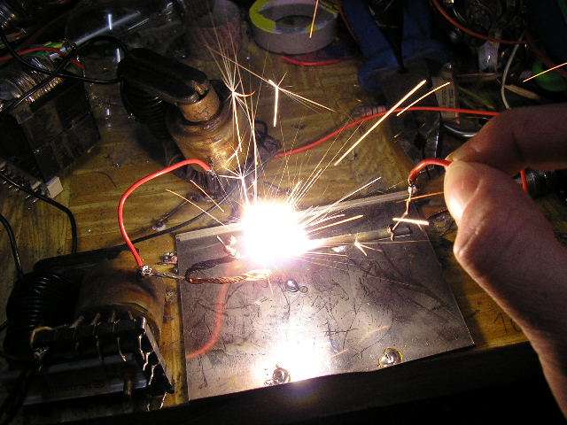
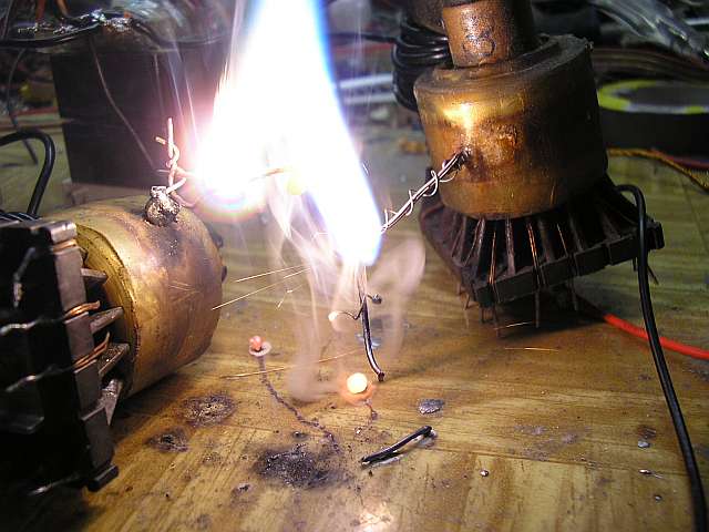
both emitors connected negative terminal. I used this inverter to drive two 8kV switching high-voltage transformers.
As a gate driver used in this experimental diagram IR2153, but can be
it converted to a circuit TL494 or SG3525 with pulse width modulation (PWM).
Warning! Entire circuit including the driver is electrically connected
to the mains and contains lethal voltage. The capacitors can remain charged to fatal voltage even after disconnected from mains.
There's a high voltage at the output. This voltage can be fatal and can break down the insulation.
Everything you do and only at your own risk.
Author does not take any responsibility for any harm of
health, life or property.

The schematic of the Push-pull inverter with BUP213 IGBT without the floating gate drive


primary waveform (measured on 1 turn, using this scope)
home


