´
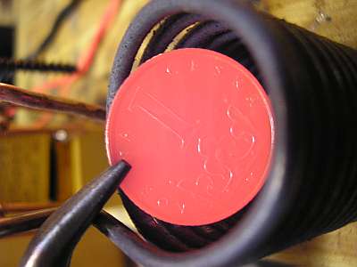
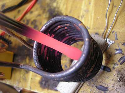
The principle of induction heating is simple. The coil creates
high-frequency electromagnetic field and metal objects in the coil or nearby induces eddy currents
that are heating it. The hysteresis losses also contribute to the heating. Even for a small coil like this a current about 100A is needed,
therefore, in parallel with the coil there's a resonant capacitance, which compensates its
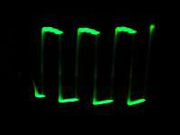
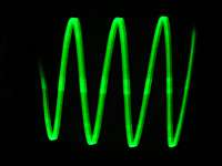
inductive character. Coil-capacitor circuit must be driven at its resonant frequency.
The drive current is much smaller than the current through the coil.
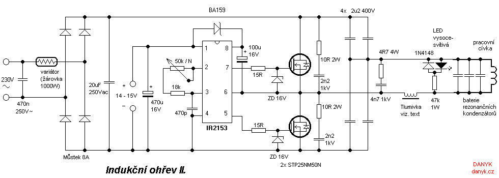
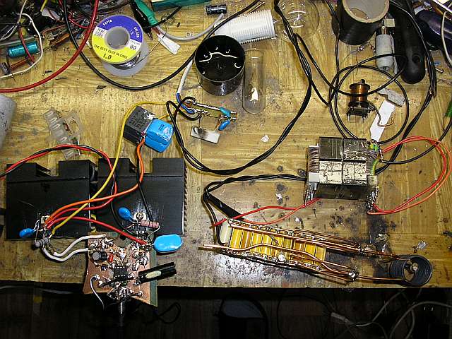
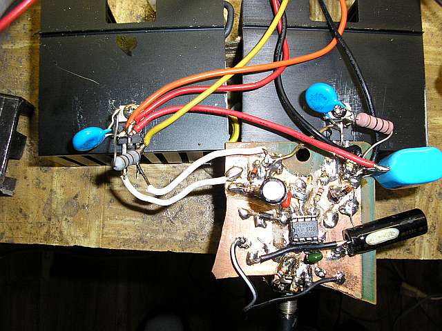
The power supply is a simple MOSFET Half Bridge controlled by circuit IR2153. The MOSFETs have a small heatsink.
Operating frequency is tuned to resonance by potentiometer. The resonance is indicated by a LED diode.
The frequency can be tuned in the range of about 22 to 90 kHz.
The control circuit needs some auxiliary voltage of 14-15V AC adapter, but
due to only few mA current you can use a simple supply with a power resistor or a capacitor.
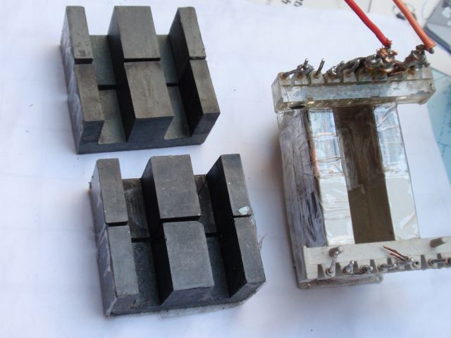
Because the output driver can not be connected directly, there's a matching choke in series.
It has 14 turns wound using four wires of 1mm diameter.
It has s ferrite core with an effective cross-section 12 x 39 mm. By adjusting the
air gap the power can be set. The induction heating is powered directly from mains.
It is using full-wave rectified voltage without filtering electrolytic capacitor.
A light bulb cca 1000W is connected in series to limit the current and save the circuit in fault condition,
overload or bad tuning. The bulb acts like a variator. MOSFETs are located on heatsinks
originally intended for older processors.
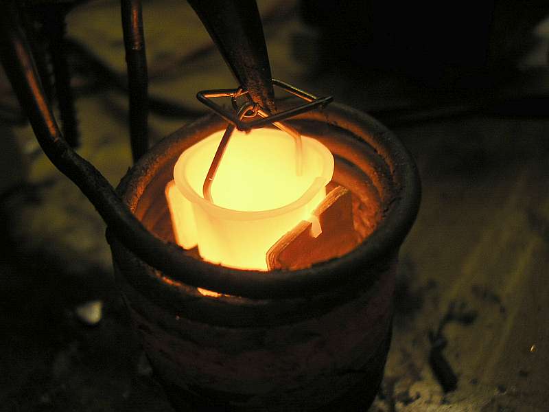
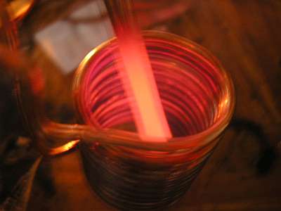
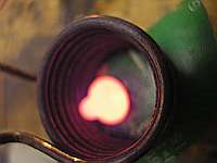
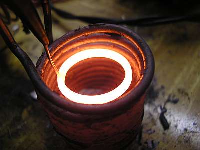
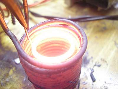
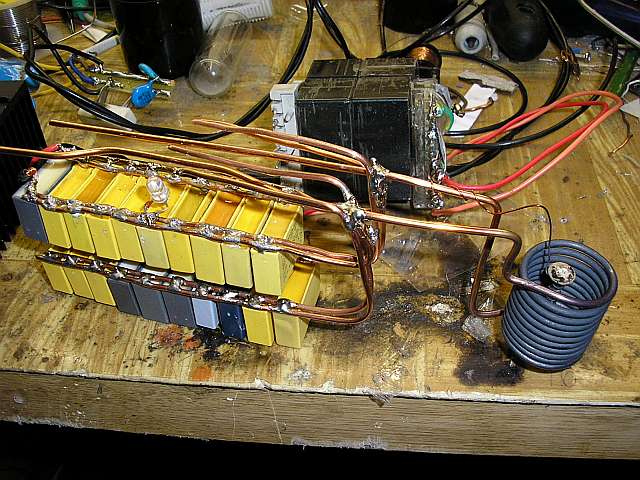
Work coil is made of wire diameter 2mm. Coil glows red after prolonged operation.
Better would be a copper tube that allows the water cooling.
Coil has 11 turns, diameter 23 mm and height 30 mm.
Capacity is due to the large current made of
many parallel capacitors (I am currently using 37 psc in parallel, the total capacity is 8u6).
The resonant frequency is 44kHz.
I also recommend:
Induction heating III. with IGBT
