Introduction:
Color temperature indicator has a wide range of applications. It can be used eg for indication of water temperature (LED shower), temperature of
different devices and power devices (amplifiers, etc.), heating appliances, temperature indicator of PC case and components, such as
CPU, graphics card, for PC tuning and car coolant temperature display in vehicles, outdoor temperature indicator (frost indicator)
signalizing proper operation of refrigerators and freezers, etc.
Color temperature indicator with 2 LEDs:
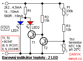
Figure 1 is a schematic of temperature indicator with two LEDs. At lower temperature the blue LED 1 is lit, at higher temperatures the red LED2 is lit.
Lower temperatures causes higher resistance of thermistor Th1. This will raise the voltage at the base of T2 and it opens. Opening T2 makes the T1 close.
Because there is no current through the LED 2, LED 1 is lit. After increasing the temperature the thermistor decreases its resistance and hence the voltage at the base of T2.
T2 is closed. As the current starts to flow into the base of T1 through R2, it opens. This causes the LED 2 to be lit. Because
both LEDs have a common resistor (R1) and the red LED 2
has a smaller voltage drop than blue LED 1, the blue LED is off. This eliminates the need for any additional transistor for LED 1.
If LED 1 does not have enough high voltage drop, it can be solved using a series diode eg 1N4007.
Potentiometer P1 sets the threshold temperature. If you can not set the desired temperature,
you may need to change the value of P1 or R3.
Color temperature indicator with 3 LEDs:
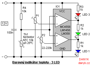
On Figure 2 there is a schematic of temperature indicator with three LEDs. At the lowest temperature blue LED 1 is lit, at higher temperatures green LED 2
and at the highest temperature the red LED 3. The measurement is performed here by double operational amplifier (OpAmp) used as comparators.
You can use the integrated circuit
eg circuit MC4558, LM1458 or LM358. The advantage of this circuit is independcy of changes in supply voltage and sharper threshold.
Temperature thresholds are set using potentiometers P1 and P2. You can use any pots with a value of about 22k to 220k.
The closer to the negative pole ir is set, the higher the temperature threshold. P2 sets the threshold
the LED 1 switches to LED 2. P1 sets the switching threshold of the LED 2 to LED 3. P1 must of course be set to a temperature higher than P2
(i.e. lower output voltage). The circuit can be easily modified to other voltages in the range of about 5 - 30V. Simply modify serial resistors of LEDs (R1, R2, R3)
for desired current. The values of resistors in the diagram (1k at 12V) corresponds to the current approx 9-10 mA. LED can be any color, their voltage drops are irrelevant.
The calculation of series resistance of LEDs for beginners is in online calculator (calculation 17).