This supply creates a high voltage of several thousand volts at a frequency of several hundred kHz.
Such voltage behaves differently than DC HV or HV of lower frequency.
Therefore, it is possible to perform experiments you can't do with other supplys.
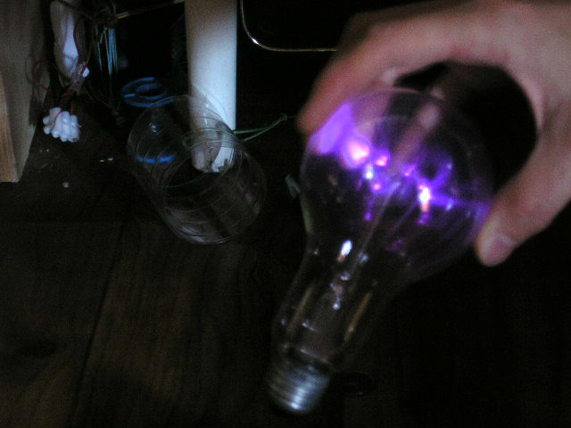
The main advantage is that this voltage thanks to the skin effect makes virtually no electric shocks, so you can touch
the output using bare metal object (!). However, the high frequency current has thermal effects and can not be
therefore directly touched (risk of burns).
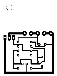
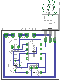
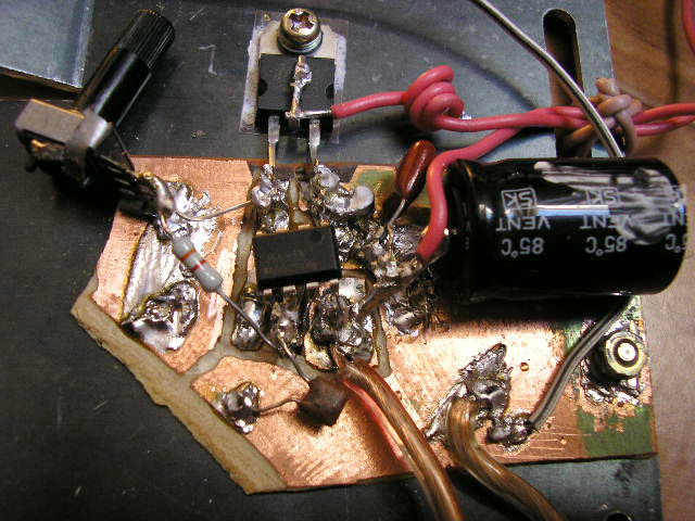
Schematic of the high frequency high voltage supply is very simple, it is a single-switch driver with
MOSFET driven through a very simple oscillator circuit with the 555.
At the output, there is no resonant capacitor as usual,
because its function takes both output and Miller capacitance of MOSFET and secondly
internal capacitance of the transformer. Operating frequency is tuned to resonance with
potentiometer. With proper tuning the output has slight corona. This high frequency high voltage supply draws about 6A.
Use N-type MOSFET, such as
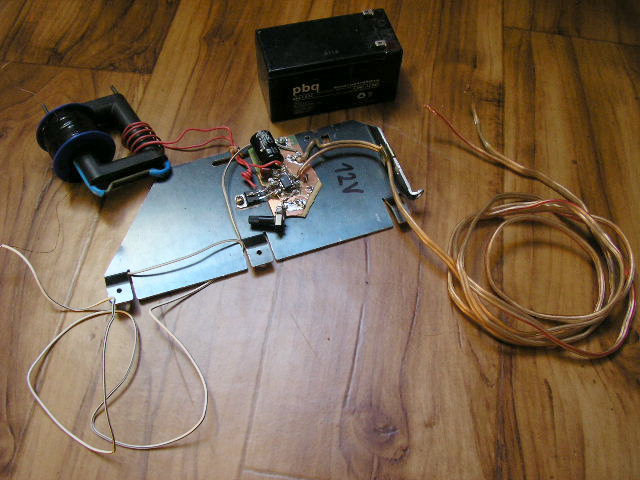
BUZ10, BUZ11, IRF530, IRF540, IRFZ44, STP24NF10 or STP36NF06. Transistor must be heat sinked. Smaller heat sink
than the one in the pictures is enough.
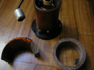
The output of the HF transformer is wound on a large ferrite core of the old TV HV transformer (LOPT).
The primary winding has 6 turns of thick insulated wire. Secondary has 300 turns of 0.4 mm diameter or less,
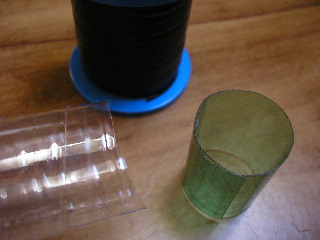
wound on the spool from solder. Winding is wound in several layers (in my case five).
In each layer are carefully made by winding turns together and must never be crossed.
Individual layers of winding must be well insulated from each other, such as strip cut-out
from a plastic bottle. Insulation must extend to the edge of the spool and must be at least two layers, otherwise
it can shoot through. Don't put turns to the edge, but leave to each side the gap around
3-4 mm. Windings must be attached by tape to prevent it from getting closer to the edge of the spool.
Attention should also be paid to the coil terminals and transitions between the layers.
If wound in five layers, on each side of the coil there are 2 transitions and one outlet. They must be
evenly spaced, ideally 120 degrees apart. Grounded is obviously the lower end of the coil.
You can certainly experiment with the number of turns, but I do not recommend less than 3 turns on primaryd.
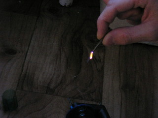
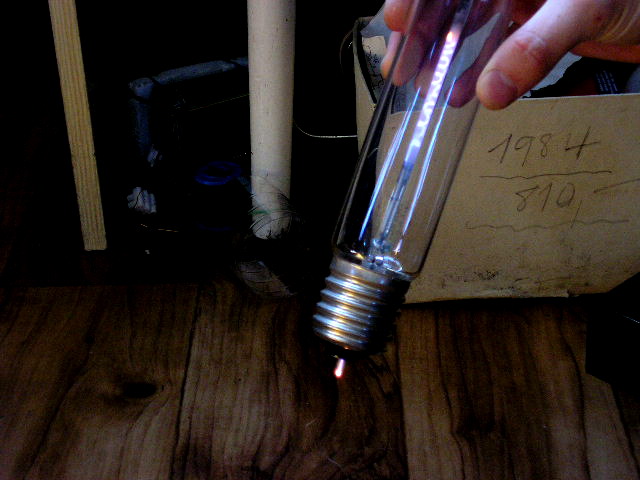
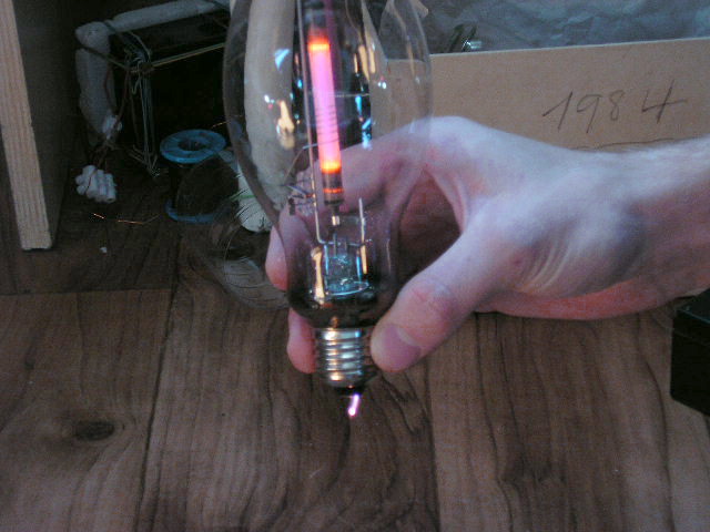
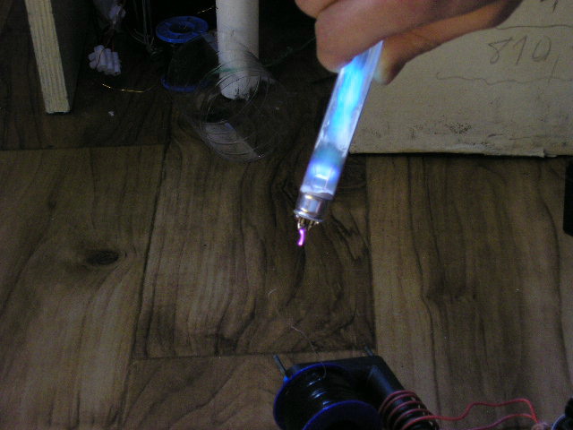
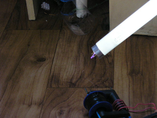
Experiments with the supply I will not longer describe. The images below are better for this purpose. Pictures are
read the best :-). Everyone can find much more possible experiements.