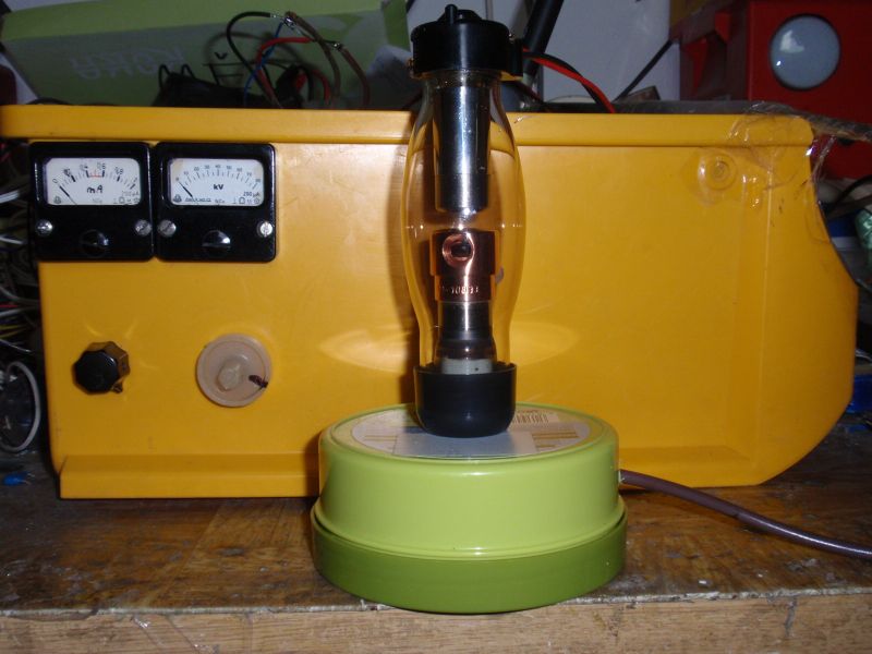
This is a switched adjustable supply of high voltage with stabilization. I built it to power x-ray tubes and X-ray
emitting vacuum tubes, which occurred in several of my articles
(
first,
second,
third,
4th).
Because this supply may also find other applications, bring its own detailed description. Suitable for example to test
insulators and dielectric strength, measuring ignition voltage of neon lamps, air and other gases, experiments with electrostatics,
lifters, tube testing, ionized air and ozone production,
etc. The maximum output current is approximately 0.7 mA.
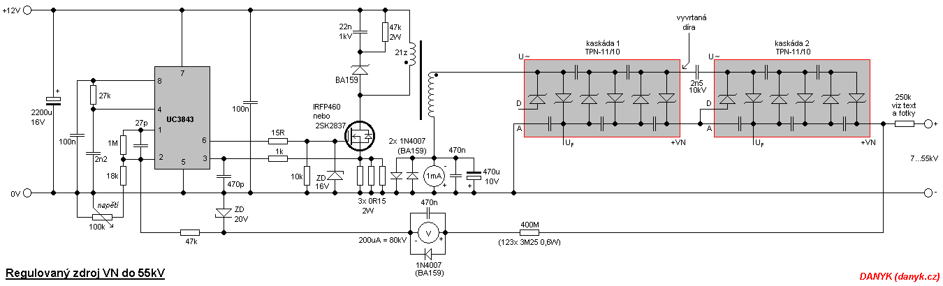
The supply is built as a single switch flyback inverter with pulse width modulation (PWM) and villard multiplier.
UC3843 is a driving circuit that provides voltage stabilization and protection against overload.
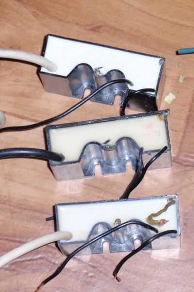
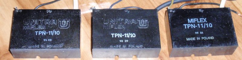
The multiplier is composed of two TPN-11/10 television cascades. The cascade
were used in color CRT television sets with SCR (thyristor) horizontal deflection. HV transformer
comes from a similar type of TV. Its output voltage is up to cca 9kV. The output voltage
is equal to 6x flyback amplitude and 5x forward amplitude. Winding orientation is therefore necessary to keep
(flyback half cycles are much smaller amplitude than forward).
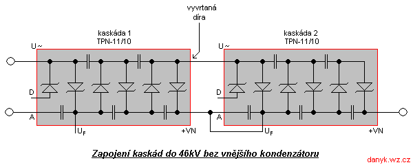
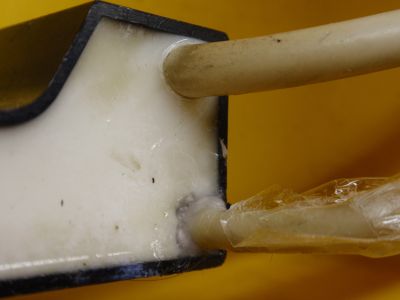
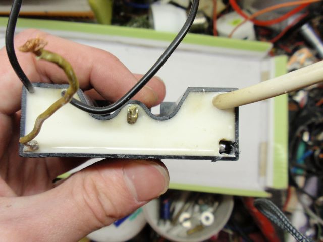
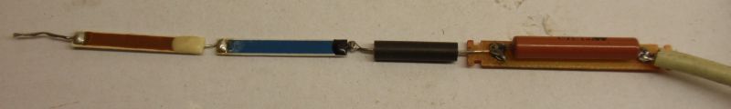
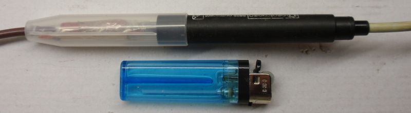
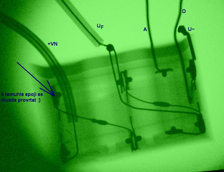
A complicating factor is that the cascade have not taken out the top end of
live chain of capacitors. At the first cascade is therefore necessary to drill to this point.
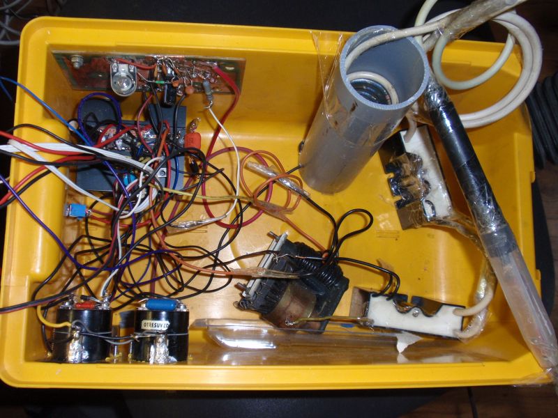
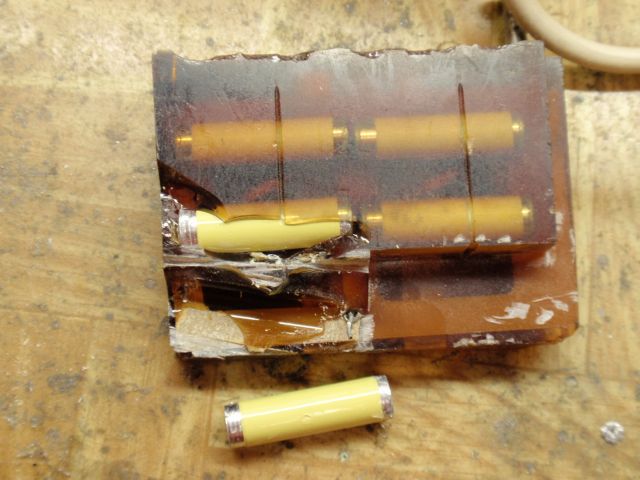
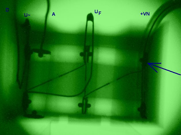
The place where I drilled, is seen in the photos below. Attach and X-ray
images of cascade, where you can see its internal structure. The maximum voltage
one cascade is 27.5 kV and maximum voltage of the two cascades is therefore 55kV.
It is necessary to involve one external high voltage capacitor.
Otherwise, you can use a modified version without this capacitor,
but the maximum output voltage must be reduced to approximately 46kV.
Resistance of 400M consists of 123 pieces of 3M25 / 0.6 W resistors and
is described in more detail
here. This resistance has 4 functions: It serves as a feedback voltage to stabilize,
as a resistor to a voltmeter, a discharge resistor for capacitor discharge after switching off and as the load resistance
when no load is connected. 250k resistor is made up of several smaller HV resistors (50 + 50 + 50 + 100 k)
from television cascades. You can also link a large number of low voltage resisi (as in the case of 400M resistance).
In addition the supply is equipped with mA meter. It measures the output current.
Milliampmeter is located in the cold end of secondary. The disadvantage is that it measures the
current through the resistance 400M. If necessary it can be put into the cold end of the load. This
connection method has the disadvantage that the load can't be of common negative pole.
The third option is to place directly into milliampmeter HV output, but its isolation would be very difficult.
Location of milliammeter is dependent on the type of load with which the supply work with. Transistor
should be placed on a heatsink. Operating frequency of this switching supply is about 12kHz.